
Article Categories
- All Categories
-
 Data Structure
-
 Networking
-
 RDBMS
RDBMS
-
 Operating System
-
 Java
Java
-
 MS Excel
-
 iOS
iOS
-
 HTML
HTML
-
 CSS
CSS
-
 Android
-
 Python
-
 C Programming
-
 C++
C++
-
 C#
C#
-
 MongoDB
-
 MySQL
MySQL
-
 Javascript
-
 PHP
PHP
-
 Economics & Finance
Race-around Condition in JK Flip-flop
Let's start this article with a brief introduction of JK flip-flop and its block diagram and truth table, before moving on to discuss the race-around condition.
JK Flip-Flop
JK flip-flops is a one-bit storage device which has two stable states. The block diagram representation of a JK flip-flops is shown in Figure-1.

It has two inputs specified by "J" and "K", one clock input for synchronization of the circuit, and two outputs represented by Q and Q'.
When clock signal is absent, the output of the JK flip-flop is independent of the inputs J and K. When the clock signal is present, the output of the JK flip-flops changes according to the inputs J and K.
The operation of the JK flip-flops can be studied from its truth table which is given as follows ?
| Inputs | Previous State | Output (Next State) | Comment | |
|---|---|---|---|---|
| J | K | Qn | Qn+1 | |
| 0 | 0 | 0 | 0 | No Change |
| 0 | 0 | 1 | 1 | No Change |
| 0 | 1 | 0 | 0 | Reset |
| 0 | 1 | 1 | 0 | Reset |
| 1 | 0 | 0 | 1 | Set |
| 1 | 0 | 1 | 1 | Set |
| 1 | 1 | 0 | 1 | Toggle |
| 1 | 1 | 1 | 0 | Toggle |
Now, let us discuss the race-around condition in the JK flip-flops.
Race-around Condition in JK Flip-flops
From the above truth table of the JK flip-flops, it can be observed that when J = 1 and K =1, then output Qn+1 = Qn', which means for inputs J = 1 and K = 1, the JK flip-flops acts as a toggle switch.
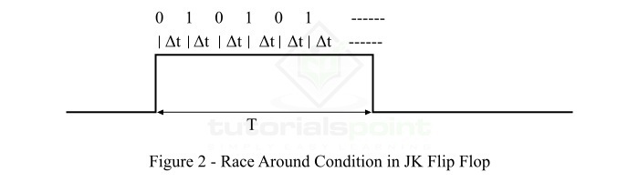
Let us consider the inputs J = 1 and K = 1, and the output Q = 0. After the propagation delay (let ?t) of the flip-flops, the output of the JK flip-flops changes from 0 to 1. As we know, the output of the JK flip-flops is connected to its inputs. Hence, the output also acts as input, and thus after the next delay (?t), the output will change from 1 to 0. This process will continue till the end of the applied clock signal. Thus, the output of the JK flip-flops is uncertain. This condition of JK flip-flops is called the race-around condition.
Race-around condition in JK flip-flops is shown in Figure-2, where T is the total duration of clock pulse.
How the Race-around Condition Can Be Avoided?
The problem of the race-around condition does not exist in the flip-flops where the inputs do not change during the presence of clock pulse. But, in the case of JK flip-flops, the inputs change during the clock pulse due to the feedback path present between inputs and outputs. Hence, in JK flip-flops, the race around condition is a major problem.
The problem of race-around condition and the uncertainty of output can be avoided by increasing the delay of the flip-flops. For that, the delay of the flip-flops must be greater than the duration of the clock signal, i.e. ?t > T. In another way, the duration of the applied clock signal (T) must be reduced to make it less than the delay of the flip-flops (?t).
However, the increase in the delay of the flip-flops is not a good practice because it decreases the speed of the system. On the other hand, it is also quite difficult to decrease the duration of the clock pulse (T) beyond the delay of the flip-flops (?t). This is because, the delay of the JK flip-flops (?t) is of the order of nanoseconds.
Hence, the most practical way to solve the problem of race-around condition in JK flip-flops is to use the JK flip-flops in the Master and Slave Mode. In the master-slave mode of JK flip-flops, two JK flip-flops are cascaded.
This is all about the race-around condition and its remedies in JK flip-flops.

35K+ Views
