- TSSN Tutorial
- TSSN - Home
- TSSN - Introduction
- TSSN - Switching Systems
- Elements of a Switching System
- TSSN - Strowger Switching System
- TSSN - Switching Mechanisms
- TSSN - Common Control
- TSSN - Touch-tone Dial Telephone
- TSSN - Crossbar Switching
- Crossbar Switch Configurations
- TSSN - Crosspoint Technology
- TSSN - Stored Program Control
- TSSN - Software Architecture
- TSSN - Switching Techniques
- TSSN - Time Division Switching
- TSSN - Telephone Networks
- TSSN - Signaling Techniques
- TSSN - ISDN
- TSSN Useful Resources
- TSSN - Quick Guide
- TSSN - Useful Resources
- TSSN - Discussion
TSSN - Telephone Networks
In this chapter, we will learn about the Public Switched Telephone Network (PSTN). This extraordinary telecommunication network is counted as one of the achievements in the field of technology advancement. However, there come a few problems when we come to these networks. We will discuss these problems in our subsequent sections.
PSTN
The Public Switched Telephone Network is understood as an aggregate of world’s circuit switched telephone networks, used for providing public telecommunication. The PSTN networks are called POTS (Plain Old Telephone Systems). These networks are operated regionally, locally, nationally and inter-nationally using telephone lines, fiber optic cables, microwave transmission links or cellular communications.
PSTN consists of switches at centralized points on the network, which act as nodes for communication between any point and any other point on the network. All the types of Switching techniques discussed previously, such as circuit switching, packet switching and message switching are different modes of using PSTN.
Subscriber Loop Systems
In a general telephone network, every subscriber has two dedicated lines connecting to the nearest switching exchange, which are called the Loop lines of that subscriber. The laying of lines to the subscriber premises from the exchange office is called Cabling. As it is difficult to run cables from each subscriber’s premises to the exchange, large cables are used through which the drop wires (subscriber lines) are taken to a distribution point.
The drop wires are connected to wire pairs at the distribution point, in the cables. Such distribution cables from nearby geographical area are connected at a same feeder point where they connected to branch feeder cables which in turn, are connected to the main feeder cable. This whole process can be understood with the help of the following figure
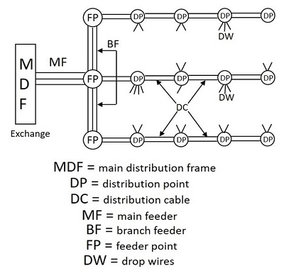
The subscriber cable pairs from the exchange will also terminate at MDF through main feeder cables that carry large number of wire pairs. These subscriber pairs and exchange pairs are interconnected at the MDF using jumpers, which makes MDF to provide flexible mechanism for reallocating cable pairs and subscriber numbers. This means a subscriber who shifts to a different location though in the same exchange area, can be allowed to use the same number using appropriate jumper, while his old drop wires can be used by another subscriber with a new number.
Switching Hierarchy and Routing
The next important system in this is the switching hierarchy and routing of the telephone lines. The interconnectivity of calls between different areas having different exchanges is done with the help of trunk lines between the exchanges. The group of trunk lines that are used to interconnect different exchanges are called the Trunk Groups.
In the process of interconnecting exchanges, there are three basic topologies, such as
- Mesh Topology
- Star Topology
- Hierarchical
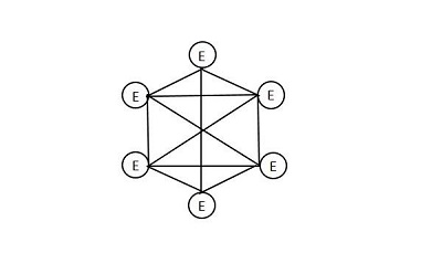
Mesh Topology
Mesh topology, as the name implies, is a fully connected network. The number of trunk groups in a mesh network is proportional to the square of the exchanges being interconnected. Hence, these mesh topologies are widely used in metropolitan areas where there is heavy traffic.
The following figure shows how a mesh topology looks like.
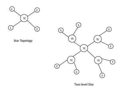
Star Topology
Star topology is connected in the shape of a star, which utilizes an intermediate exchange called a tandem exchange through which all other exchanges communicate. The figure given below shows the model of a star network. The star network is used when traffic levels are comparatively low. Many star networks can be used by interconnecting through additional tandem exchange, leading to a two-level star network as shown in the following figure.
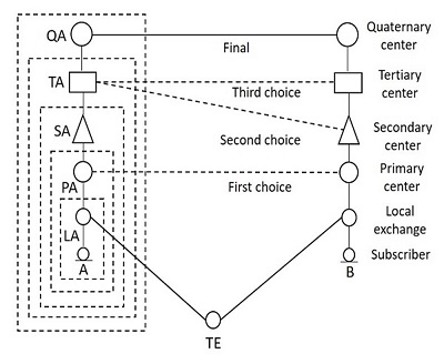
Hierarchical
The hierarchical topology is used to handle heavy traffic with minimal number of trunk groups. The traffic flows through the Final route which is the highest level of hierarchy. If the traffic intensity between any pair of exchanges is high, direct trunk routes may be established between them as indicated by dashed lines in the figure given below. These direct trunk routes are High Usage routes. Wherever these high usage routes exist, the traffic flows through them. Here, the overflown traffic is routed along the hierarchical path. No overflow traffic is permitted from the final route.
To decide the routing on a particular connection, the following three methods are used −
- Right-through routing
- Own-exchange routing
- Computer-controlled routing
Transmission Plan
The Transmission of signals through cables should be high in quality in order to ensure better communication. The transmission links between national and international circuits should be better to connect in tandem for establishing calls.
To have high quality standards, the following guidelines were put forward by the CCITT −
The maximum number of circuits to be used in an international call is 12.
No more than four international circuits be used in tandem between the originating and the terminating international switching centers.
In exceptional cases and for a low number of calls, the total number of circuits may be 14, but even in this case, the international circuits are limited to a maximum of four.
Along with limiting the number of circuits required, the losses such as line loss or wire loss and switch loss or contact loss should also be minimized. These aspects come under the transmission loss budget, which provides for factors such as keeping echo levels within limits and control singing.
Because of the long distances, the circuits need amplifiers and repeaters at appropriate intervals to boost the signals. At the subscriber-line interfaces, mismatch occurs; this results in reflecting a part of the incoming signal onto the outgoing circuit, which returns to the speaker as Echo. The echo suppressor or cancellation circuits are used to minimize the effect of the echo. The signal attenuation and echo are the main losses in the transmission lines along with contact and wire losses.
Transmission Systems
There are different types of transmission systems such as Radio systems, Coaxial cable systems and Optical fiber systems being the prominent ones. As the length of the transmission distance increases, the mode of transmission also gets changed.
The signal transmission advanced from wire transmission to wireless transmission. The Radio systems provide wireless transmission, the coaxial cable systems allow transmission of signal through wire and the fiber optic systems provide communication through optical fibers.
Depending upon the mechanism of signal propagation, the Radio communication has four varieties of communication, such as −
- Skywave or Ionospheric Communication
- Line-of-sight (LOS) microwave communication limited by horizon
- Tropospheric Scatter Communication
- Satellite Communication
Numbering Plan
During the early stages of development, the numbering scheme was confined to a small single exchange, which used to connect to the other exchanges by identifying them with the names of the towns in which they were located. But with the increase in the number of subscribers, many exchanges were introduced.
A large central exchange which serves the main business center of a town, can be called the Main Exchange and the smaller exchanges serving different localities are called the Satellite Exchanges. The area containing the complete network of the main exchange and the satellites is known as the Multi-exchange area. A common numbering scheme was required to identify the location of the exchange of called subscriber, especially when the call is from a location outside the Multi-exchange area.
The common numbering scheme is called the Linked Numbering Scheme, where all the exchanges in a town were collectively identified by the name of the town. With the introduction of Subscriber Trunk Dialing (STD) or Direct Distance Dialing (DDD) for inter-city and inter-town long distance communications, the Multi-exchange areas were also allotted unique identification number. In order to make very long distance communications possible, the international dialing called the International Subscriber Dialing (ISD) was introduced, where the international numbering plan and national numbering plan came into existence.
Types of Numbering Plans
In this section, we will discuss the Numbering Plans for telephone networks. The plans are described in brief below −
Open Numbering Plan
This is also called the Non-Uniform Numbering Plan and it permits wide variation in the number of digits to be used to identify a subscriber within a multi-exchange area or within a country.
Semi-Open Numbering Plan
This plan permits number lengths to differ by almost one or two digits. The semi-open numbering plan is commonly used in countries such as India, Sweden, Switzerland and UK.
Closed Numbering Plan
This is also called the Uniform Numbering Plan where the number of digits in a subscriber number are fixed. This is used in a few countries such as France, Belgium, Canada, Hawaii and in a few parts of USA.
An International Numbering Plan or World Numbering Plan has been defined by the CCITT. For numbering purposes, the world is divided into zones. The following figure indicates the telephone number structure.
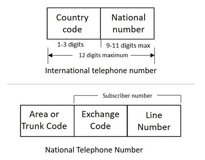
A national number consists of three parts. The parts are described below −
The Area Code or the Trunk Code
This code identifies a particular numbering area or the multi-exchange area of the called subscriber. It is with this code, the routing for a trunk call is determined and charged for it.
Exchange Code
This code identifies a particular exchange within a numbering area. It determines the routing for incoming trunk call from another numbering area or for a call originating from one exchange and destined to another in the same numbering area.
Subscriber Line Number
It is used to select the called subscriber line at the terminating exchange. The combination of the exchange code and the subscriber line number is called the Subscriber Line number in CCITT terminology.
Charging Plan
The calls are charged as accounted by the metering instrument connected to each subscriber line or as per a metering register that is assigned to each subscriber in case of electronic exchanges. A meter counts the number of charging units, and that count is incremented by sending a pulse to the meter. For the number of units, the meter reads, a bill is raised by assigning a rate to the charging unit.
The individual calls can be charged based on the following categories.
- Duration independent charging
- Duration dependent charging
Local calls within a numbering area are usually charged on a duration independent basis. For duration dependent charging, the meter starts incrementing, once the called subscriber answers the call. Depending upon the number of exchanges involved in setting up a call, more than one pulse is sent to the charging meter, which is called Multi-Metering. The metering pulse rate keeps on increasing per min with the distance between the called and the calling subscribers.