- TSSN Tutorial
- TSSN - Home
- TSSN - Introduction
- TSSN - Switching Systems
- Elements of a Switching System
- TSSN - Strowger Switching System
- TSSN - Switching Mechanisms
- TSSN - Common Control
- TSSN - Touch-tone Dial Telephone
- TSSN - Crossbar Switching
- Crossbar Switch Configurations
- TSSN - Crosspoint Technology
- TSSN - Stored Program Control
- TSSN - Software Architecture
- TSSN - Switching Techniques
- TSSN - Time Division Switching
- TSSN - Telephone Networks
- TSSN - Signaling Techniques
- TSSN - ISDN
- TSSN Useful Resources
- TSSN - Quick Guide
- TSSN - Useful Resources
- TSSN - Discussion
TSSN - Crossbar Switching
In this chapter, we will discuss the concept of Crossbar Switching. The Crossbar exchanges were developed during 1940s. They achieve full access and non-blocking capabilities with the Crossbar switches and common control equipment, used in the Crossbar exchanges. The active elements called Crosspoints are placed between the input and the output lines. In the common control switching systems, the separation between switching and control operations allows the usage of switching networks by a group of common control switches to establish many calls at the same time on a shared basis.
The Features of Crossbar Switches
In this section, we will discuss the different features of the Crossbar Switches. The features are described in brief below −
While processing a call, the common control system helps in the sharing of resources.
The specific route functions of call processing are hardwired because of the Wire logic computers.
The flexible system design helps in the appropriate ratio selection is allowed for a specific switch.
Fewer moving parts ease the maintenance of Crossbar switching systems.
The Crossbar switching system uses the common control networks which enable the switching network to perform event monitoring, call processing, charging, operation and maintenance as discussed previously. The common control also provides uniform numbering of subscribers in a multi-exchange area like big cities and routing of calls from one exchange to another using the same intermediate exchanges. This method helps to avoid the disadvantages associated with the step-by-step switching method through its unique process of receiving and storing the complete number to establish a call connection.
Crossbar Switching Matrix
The Crossbar arrangement is a matrix which is formed by the M X N sets of contacts arranged as vertical and horizontal bars with contact points where they meet. They need nearly M + N number of activators to select one of the contacts. The Crossbar matrix arrangement is shown in the following figure.
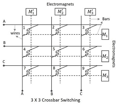
The Crossbar matrix contains an array of horizontal and vertical wires shown by solid lines in the following figure, which are both connected to initially separated contact points of switches. The horizontal and vertical bars shown in dotted lines in the above figure are mechanically connected to these contact points and attached to the electromagnets.
The Crosspoints placed between the input and the output lines have electromagnets which when energized, close the contact of intersection of the two bars. This makes the two bars to come closer and hold on. The following figure will help you understand the contact made at the Crosspoints.
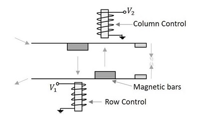
Once energized, the electromagnets pull the small magnetic slabs present on the bars. The column control electromagnet pulls the magnet on the lower bar, while the row controlelectromagnet pulls the magnet on the upper bar. In order to avoid the catching of different Crosspoints in the same circuit, a procedure is followed, to establish a connection. According to this procedure, either horizontal or vertical bar can be energized first to make a contact. However, to break a contact, the horizontal bar is de-energized first; the vertical bar being de-energized follows this.
As all the stations are allowed to be connected with all possible connections as long as the called party is free, this Crossbar Switching is called the Non-Blocking Crossbar configuration, which requires N2 switching elements for N subscribers. So, the Crosspoints will be highly greater than the subscribers. For example, 100 subscribers will require a 10,000 Crosspoints. This means that this technique can be applied to a group having a small number of subscribers.
There is an external switch called the Marker; this can control many switches and serve many registers. The switch decides the operation of magnets such as the select magnet and the bridge magnet that should be energized and de-energized for connecting and releasing the subscriber respectively.
Diagonal Crosspoint Matrix
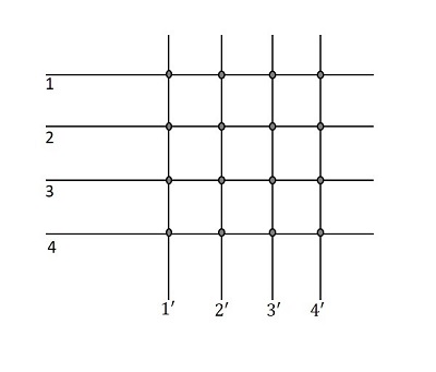
In the matrix, as 1,2,3,4 indicate input lines and 1’,2’,3’,4’ indicate output lines of the same subscribers, if a connection has to be established between the 1st and the 2nd subscriber, then 1 and 2’ can be connected or 2 and 1’ can be connected using the Crosspoints. In the same way, when a connection has to be established between 3 and 4, then 3-4’ Crosspoint or 4-3’ Crosspoint can do the work. The following figure will help you understand how this works.
Now, the diagonal portions are the Crosspoints connecting to the same subscriber again. A line that is already connected to the terminal has no need of connecting it again to the same terminal. Hence, the diagonal points are also not necessary.
So, it is understood that for N number of subscribers, if the diagonal points are also considered, the total number of Crosspoints will be,
$$\frac{N\left ( N+1 \right )}{2}$$
For N number of subscribers, if the diagonal points are not considered, then the total number of Crosspoints will be,
$$\frac{N\left ( N-1 \right )}{2}$$
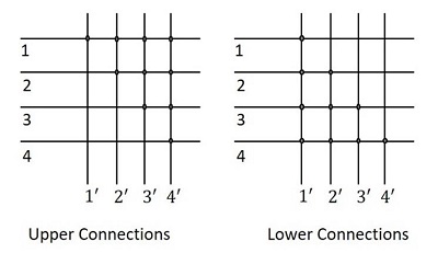
As the number of nodes N increases, the Crosspoints proportionally increase up to N2. The Crosspoints will always be linear. Therefore, as either the lower part or the upper part of the diagonal points in the matrix, can be considered, the whole matrix considering the lower portion, will now be as shown in the following figure.
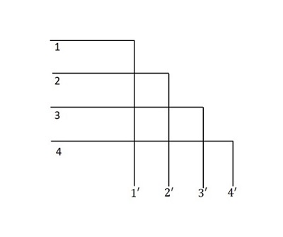
This is called the Diagonal Crosspoint Matrix. The matrix is in a triangular format and can be called the Triangular Matrix or the Two-way Matrix. The diagonal Crosspoint
matrix is fully connected. When the third subscriber initiates a call, to the fourth subscriber, then the third subscriber’s horizontal bar is initiated first and then the fourth subscriber’s vertical bar is energized. The diagonal Crosspoint matrix is a non-blocking configuration. The main disadvantage of this system is that, the failure of a single switch will make some subscribers inaccessible.
The Crosspoint switch is the abstract of any switch such as the time or space switch. If N connections can be made simultaneously in an NXN switch matrix, it is called the Non-blocking Switch. If the number of connections made are less than N in some or all cases, then it is called the Blocking switch. These blocking switches are worked upon using Multiple Switches and such networks are called Line frames.