- Linear Integrated Circuits Applications
- Home
- Basics of Integrated Circuits Applications
- Basics Operational Amplifier
- Op-Amp applications
- Arithmetic Circuits
- Differentiator & Integrator
- Converters Of Electrical Quantities
- Comparators
- Log & Anti-Log Amplifiers
- Rectifiers
- Clippers
- Clampers
- Active Filters
- Sinusoidal Oscillators
- Waveform Generators
- 555 Timer
- Phase Locked Loop Ic
- Voltage Regulators
- Data Converters
- Digital to Analog Converters
- DAC Example Problem
- Direct Type ADCs
- Indirect Type ADC
- Useful Resources
- Quick Guide
- Useful Resources
- Discussion
Op-Amp-Applications
A circuit is said to be linear, if there exists a linear relationship between its input and the output. Similarly, a circuit is said to be non-linear, if there exists a non-linear relationship between its input and output.
Op-amps can be used in both linear and non-linear applications. The following are the basic applications of op-amp −
- Inverting Amplifier
- Non-inverting Amplifier
- Voltage follower
This chapter discusses these basic applications in detail.
Inverting Amplifier
An inverting amplifier takes the input through its inverting terminal through a resistor $R_{1}$, and produces its amplified version as the output. This amplifier not only amplifies the input but also inverts it (changes its sign).
The circuit diagram of an inverting amplifier is shown in the following figure −
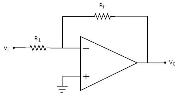
Note that for an op-amp, the voltage at the inverting input terminal is equal to the voltage at its non-inverting input terminal. Physically, there is no short between those two terminals but virtually, they are in short with each other.
In the circuit shown above, the non-inverting input terminal is connected to ground. That means zero volts is applied at the non-inverting input terminal of the op-amp.
According to the virtual short concept, the voltage at the inverting input terminal of an op-amp will be zero volts.
The nodal equation at this terminal's node is as shown below −
$$\frac{0-V_i}{R_1}+ \frac{0-V_0}{R_f}=0$$
$$=>\frac{-V_i}{R_1}= \frac{V_0}{R_f}$$
$$=>V_{0}=\left(\frac{-R_f}{R_1}\right)V_{t}$$
$$=>\frac{V_0}{V_i}= \frac{-R_f}{R_1}$$
The ratio of the output voltage $V_{0}$ and the input voltage $V_{i}$ is the voltage-gain or gain of the amplifier. Therefore, the gain of inverting amplifier is equal to $-\frac{R_f}{R_1}$.
Note that the gain of the inverting amplifier is having a negative sign. It indicates that there exists a 1800 phase difference between the input and the output.
Non-Inverting Amplifier
A non-inverting amplifier takes the input through its non-inverting terminal, and produces its amplified version as the output. As the name suggests, this amplifier just amplifies the input, without inverting or changing the sign of the output.
The circuit diagram of a non-inverting amplifier is shown in the following figure −

In the above circuit, the input voltage $V_{i}$ is directly applied to the non-inverting input terminal of op-amp. So, the voltage at the non-inverting input terminal of the op-amp will be $V_{i}$.
By using voltage division principle, we can calculate the voltage at the inverting input terminal of the op-amp as shown below −
$$=>V_{1} = V_{0}\left(\frac{R_1}{R_1+R_f}\right)$$
According to the virtual short concept, the voltage at the inverting input terminal of an op-amp is same as that of the voltage at its non-inverting input terminal.
$$=>V_{1} = V_{i}$$
$$=>V_{0}\left(\frac{R_1}{R_1+R_f}\right)=V_{i}$$
$$=>\frac{V_0}{V_i}=\frac{R_1+R_f}{R_1}$$
$$=>\frac{V_0}{V_i}=1+\frac{R_f}{R_1}$$
Now, the ratio of output voltage $V_{0}$ and input voltage $V_{i}$ or the voltage-gain or gain of the non-inverting amplifier is equal to $1+\frac{R_f}{R_1}$.
Note that the gain of the non-inverting amplifier is having a positive sign. It indicates that there is no phase difference between the input and the output.
Voltage follower
A voltage follower is an electronic circuit, which produces an output that follows the input voltage. It is a special case of non-inverting amplifier.
If we consider the value of feedback resistor, $R_{f}$ as zero ohms and (or) the value of resistor, 1 as infinity ohms, then a non-inverting amplifier becomes a voltage follower. The circuit diagram of a voltage follower is shown in the following figure −
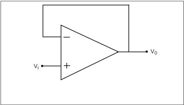
In the above circuit, the input voltage $V_{i}$ is directly applied to the non-inverting input terminal of the op-amp. So, the voltage at the non-inverting input terminal of op-amp is equal to $V_{i}$. Here, the output is directly connected to the inverting input terminal of opamp. Hence, the voltage at the inverting input terminal of op-amp is equal to $V_{0}$.
According to the virtual short concept, the voltage at the inverting input terminal of the op-amp is same as that of the voltage at its non-inverting input terminal.
$$=>V_{0} = V_{i}$$
So, the output voltage $V_{0}$ of a voltage follower is equal to its input voltage $V_{i}$.
Thus, the gain of a voltage follower is equal to one since, both output voltage $V_{0}$ and input voltage $V_{i}$ of voltage follower are same.