- UML Tutorial
- UML - Home
- UML - Overview
- UML - Building Blocks
- UML - Architecture
- UML - Modeling Types
- UML - Basic Notations
- UML - Standard Diagrams
- UML - Class Diagram
- UML - Object Diagram
- UML - Component Diagram
- UML - Deployment Diagram
- UML - Use Case Diagram
- UML - Interaction Diagram
- UML - Statechart Diagram
- UML - Activity Diagram
- UML - Summary
- UML 2.0 Overview
- UML 2.0 - Overview
- UML Useful Resources
- UML - Useful Resources
- UML - Knowledge Test
- Utilities
- UML - Tools & Utilities
- UML - Discussion
UML - Interaction Diagrams
From the term Interaction, it is clear that the diagram is used to describe some type of interactions among the different elements in the model. This interaction is a part of dynamic behavior of the system.
This interactive behavior is represented in UML by two diagrams known as Sequence diagram and Collaboration diagram. The basic purpose of both the diagrams are similar.
Sequence diagram emphasizes on time sequence of messages and collaboration diagram emphasizes on the structural organization of the objects that send and receive messages.
Purpose of Interaction Diagrams
The purpose of interaction diagrams is to visualize the interactive behavior of the system. Visualizing the interaction is a difficult task. Hence, the solution is to use different types of models to capture the different aspects of the interaction.
Sequence and collaboration diagrams are used to capture the dynamic nature but from a different angle.
The purpose of interaction diagram is −
To capture the dynamic behaviour of a system.
To describe the message flow in the system.
To describe the structural organization of the objects.
To describe the interaction among objects.
How to Draw an Interaction Diagram?
As we have already discussed, the purpose of interaction diagrams is to capture the dynamic aspect of a system. So to capture the dynamic aspect, we need to understand what a dynamic aspect is and how it is visualized. Dynamic aspect can be defined as the snapshot of the running system at a particular moment
We have two types of interaction diagrams in UML. One is the sequence diagram and the other is the collaboration diagram. The sequence diagram captures the time sequence of the message flow from one object to another and the collaboration diagram describes the organization of objects in a system taking part in the message flow.
Following things are to be identified clearly before drawing the interaction diagram
Objects taking part in the interaction.
Message flows among the objects.
The sequence in which the messages are flowing.
Object organization.
Following are two interaction diagrams modeling the order management system. The first diagram is a sequence diagram and the second is a collaboration diagram
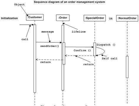
The Sequence Diagram
The sequence diagram has four objects (Customer, Order, SpecialOrder and NormalOrder).
The following diagram shows the message sequence for SpecialOrder object and the same can be used in case of NormalOrder object. It is important to understand the time sequence of message flows. The message flow is nothing but a method call of an object.
The first call is sendOrder () which is a method of Order object. The next call is confirm () which is a method of SpecialOrder object and the last call is Dispatch () which is a method of SpecialOrder object. The following diagram mainly describes the method calls from one object to another, and this is also the actual scenario when the system is running.
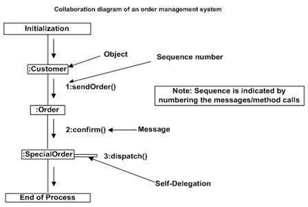
The Collaboration Diagram
The second interaction diagram is the collaboration diagram. It shows the object organization as seen in the following diagram. In the collaboration diagram, the method call sequence is indicated by some numbering technique. The number indicates how the methods are called one after another. We have taken the same order management system to describe the collaboration diagram.
Method calls are similar to that of a sequence diagram. However, difference being the sequence diagram does not describe the object organization, whereas the collaboration diagram shows the object organization.
To choose between these two diagrams, emphasis is placed on the type of requirement. If the time sequence is important, then the sequence diagram is used. If organization is required, then collaboration diagram is used.
Where to Use Interaction Diagrams?
We have already discussed that interaction diagrams are used to describe the dynamic nature of a system. Now, we will look into the practical scenarios where these diagrams are used. To understand the practical application, we need to understand the basic nature of sequence and collaboration diagram.
The main purpose of both the diagrams are similar as they are used to capture the dynamic behavior of a system. However, the specific purpose is more important to clarify and understand.
Sequence diagrams are used to capture the order of messages flowing from one object to another. Collaboration diagrams are used to describe the structural organization of the objects taking part in the interaction. A single diagram is not sufficient to describe the dynamic aspect of an entire system, so a set of diagrams are used to capture it as a whole.
Interaction diagrams are used when we want to understand the message flow and the structural organization. Message flow means the sequence of control flow from one object to another. Structural organization means the visual organization of the elements in a system.
Interaction diagrams can be used −
To model the flow of control by time sequence.
To model the flow of control by structural organizations.
For forward engineering.
For reverse engineering.