- Power Electronics Tutorial
- Power Electronics - Home
- Power Electronics - Introduction
- Power Electronics - Switching Devices
- Linear Circuit Elements
- Power Semiconductor Devices
- Silicon Controlled Rectifier
- Power Electronics - TRIAC
- Power Electronics - BJT
- Power Electronics - IGBT
- Power Electronics - MOSFET
- Solved Example
- Phase Controlled Converters
- Power Electronics - Pulse Converters
- Effect of Source Inductance
- Performance Parameters
- Reactive Power Control of Converters
- Power Electronics - Dual Converters
- Solved Example
- DC to DC Converters
- Power Electronics - Choppers
- Power Electronics - Control Methods
- Resonant Switching
- DC Converters Solved Example
- AC to DC Converters
- Single Phase AC Voltage Controllers
- Power Electronics - Cycloconverters
- Integral Cycle Control
- Power Electronics - Matrix Converters
- Solved Example
- Power Electronics Resources
- Power Electronics - Quick Guide
- Power Electronics - Useful Resources
- Power Electronics - Discussion
Power Electronics - Types of Inverters
An inverter refers to a power electronic device that converts power in DC form to AC form at the required frequency and voltage output.
Inverters are classified into two main categories −
Voltage Source Inverter (VSI) − The voltage source inverter has stiff DC source voltage that is the DC voltage has limited or zero impedance at the inverter input terminals.
Current Source Inverter (CSI) − A current source inverter is supplied with a variable current from a DC source that has high impedance. The resulting current waves are not influenced by the load.
Single Phase Inverter
There are two types of single phase inverters − full bridge inverter and half bridge inverter.
Half Bridge Inverter
This type of inverter is the basic building block of a full bridge inverter. It contains two switches and each of its capacitors has a voltage output equal to $\frac{V_{dc}}{2}$. In addition, the switches complement each other, that is, if one is switched ON the other one goes OFF.
Full Bridge Inverter
This inverter circuit converts DC to AC. It achieves this by closing and opening the switches in the right sequence. It has four different operating states which are based on which switches are closed.
Three Phase Inverter
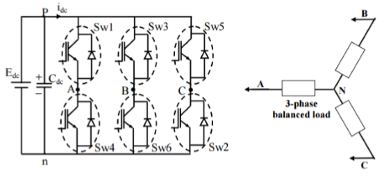
A three-phase inverter converts a DC input into a three-phase AC output. Its three arms are normally delayed by an angle of 120° so as to generate a three-phase AC supply. The inverter switches each has a ratio of 50% and switching occurs after every T/6 of the time T (60° angle interval). The switches S1 and S4, the switches S2 and S5 and switches S3 and S6 complement each other.
The figure below shows a circuit for a three phase inverter. It is nothing but three single phase inverters put across the same DC source. The pole voltages in a three phase inverter are equal to the pole voltages in single phase half bridge inverter.
The two types of inverters above have two modes of conduction − 180° mode of conduction and 120° mode of conduction.
180° mode of conduction
In this mode of conduction, every device is in conduction state for 180° where they are switched ON at 60° intervals. The terminals A, B and C are the output terminals of the bridge that are connected to the three-phase delta or star connection of the load.
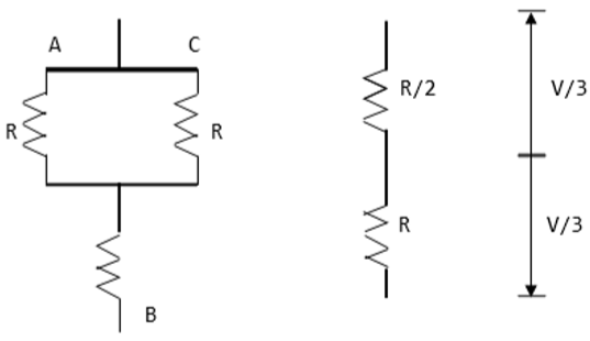
The operation of a balanced star connected load is explained in the diagram below. For the period 0° − 60° the points S1, S5 and S6 are in conduction mode. The terminals A and C of the load are connected to the source at its positive point. The terminal B is connected to the source at its negative point. In addition, resistances R/2 is between the neutral and the positive end while resistance R is between the neutral and the negative terminal.
|
The load voltages are gives as follows; VAN = V/3, VBN = −2V/3, VCN = V/3 |
The line voltages are given as follows; VAB = VAN − VBN = V, VBC = VBN − VCN = −V, VCA = VCN − VAN = 0 |
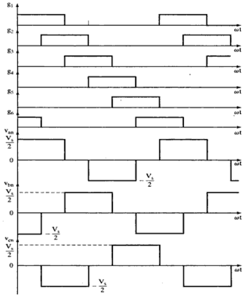
Waveforms for 180° mode of conduction
120° mode of conduction
In this mode of conduction, each electronic device is in a conduction state for 120°. It is most suitable for a delta connection in a load because it results in a six-step type of waveform across any of its phases. Therefore, at any instant only two devices are conducting because each device conducts at only 120°.
The terminal A on the load is connected to the positive end while the terminal B is connected to the negative end of the source. The terminal C on the load is in a condition called floating state. Furthermore, the phase voltages are equal to the load voltages as shown below.
Phase voltages = Line voltages
VAB = V
VBC = −V/2
VCA = −V/2
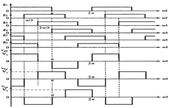
Waveforms for 120° mode of conduction