- Network Security Tutorial
- Network Security - Home
- Network Security – Overview
- Network Security – Application Layer
- Network Security – Transport Layer
- Network Security – Network Layer
- Network Security – Data Link Layer
- Network Security – Access Control
- Network Security – Firewalls
- Network Security – Critical Necessity
- Network Security Useful Resources
- Network Security - Quick Guide
- Network Security - Useful Resources
- Network Security - Discussion
Network Security – Data Link Layer
We have seen that rapid growth of Internet has raised a major concern for network security. Several methods have been developed to provide security in the application, transport, or network layer of a network.
Many organizations incorporate security measures at higher OSI layers, from application layer all the way down to IP layer. However, one area generally left unattended is hardening of Data Link layer. This can open the network to a variety of attacks and compromises.
In this chapter, we will discuss security problems at Data Link Layer and methods to counter them. Our discussion will be focused on Ethernet network.
Security Concerns in Data Link Layer
Data link Layer in Ethernet networks is highly prone to several attacks. The most common attacks are −
ARP Spoofing
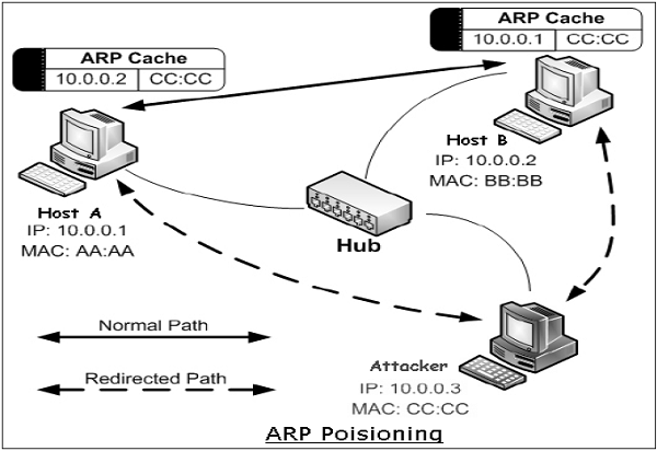
Address Resolution Protocol (ARP) is a protocol used to map an IP address to a physical machine address recognizable in the local Ethernet. When a host machine needs to find a physical Media Access Control (MAC) address for an IP address, it broadcasts an ARP request. The other host that owns the IP address sends an ARP reply message with its physical address.
Each host machine on network maintains a table, called ‘ARP cache’. The table holds the IP address and associated MAC addresses of other host on the network.
Since ARP is a stateless protocol, every time a host gets an ARP reply from another host, even though it has not sent an ARP request, it accepts that ARP entry and updates its ARP cache. The process of modifying a target host’s ARP cache with a forged entry known as ARP poisoning or ARP spoofing.
ARP spoofing may allow an attacker to masquerade as legitimate host and then intercept data frames on a network, modify or stop them. Often the attack is used to launch other attacks such as man-in-the-middle, session hijacking, or denial of service.
MAC Flooding
Every switch in the Ethernet has a Content-Addressable Memory (CAM) table that stores the MAC addresses, switch port numbers, and other information. The table has a fixed size. In the MAC flooding attack, the attacker floods the switch with MAC addresses using forged ARP packets until the CAM table is full.
Once CAM is flooded, the switch goes into hub-like mode and starts broadcasting the traffic that do not have CAM entry. The attacker who is on the same network, now receives all the frames which were destined only for a specific host.
Port Stealing
Ethernet switches have the ability to learn and bind MAC addresses to ports. When a switch receives traffic from a port with a MAC source address, it binds the port number and that MAC address.
The port stealing attack exploits this ability of the switches. The attacker floods the switch with forged ARP frames with the target host’s MAC address as the source address. Switch is fooled to believe that the target host is on port, on which actually an attacker is connected.
Now all data frames intended for the targeted host are sent to the attacker’s switch port and not to the target host. Thus, the attacker now receives all the frames which were actually destined only for the target host.
DHCP Attacks
Dynamic Host Configuration Protocol (DHCP) is not a datalink protocol but solutions to DHCP attacks are also useful to thwart Layer 2 attacks.
DHCP is used to dynamically allocate IP addresses to computers for a specific time period. It is possible to attack DHCP servers by causing denial of service in the network or by impersonating the DHCP server. In a DHCP starvation attack, the attacker requests all of the available DHCP addresses. This results in a denial of service to the legitimate host on the network.
In DHCP spoofing attack, the attacker can deploy a rogue DHCP server to provide addresses to the clients. Here, the attacker can provide the host machines with a rouge default gateway with the DHCP responses. Data frames from the host are now guided to rouge gateway where the attacker can intercept all package and reply to actual gateway or drop them.
Other Attacks
In addition to above popular attacks, there are other attacks such as Layer 2-based broadcasting, Denial of Service (DoS), MAC cloning.
In the broadcasting attack, the attacker sends spoofed ARP replies to the hosts on the network. These ARP replies set the MAC address of the default gateway to the broadcast address. This causes all the outbound traffic to get broadcast, enabling sniffing by the attacker sitting on the same Ethernet. This type of attack also affects the network capacity.
In the Layer 2-based DoS attacks, the attacker updates the ARP caches of hosts in the network with non-existent MAC addresses. The MAC address of each network interface card in a network is supposed to be globally unique. However, it can easily be changed by enabling MAC cloning. The attacker disables the target host through DoS attack and then uses the IP and MAC addresses of the targeted host.
The attacker executes the attacks to launch the higher level attacks in order to jeopardize the security of information traveling on network. He can intercept all the frames and would be able to read the frame data. The attacker can act as a man-in-middle and modify data or simply drop the frame leading to DoS. He can hijack the ongoing session between the target host and other machines, and communicate wrong information altogether.
Securing Ethernet LANs
We discussed some widely known attacks at Data Link Layer in the previous section. Several methods have been developed to mitigate these types of attacks. Some of the important methods are −
Port Security
It is a layer 2 security feature available on intelligent Ethernet switches. It involves tying a physical port of a switch to a specific MAC address/es. Anyone can access an unsecure network by simply connecting the host to one of the available switch ports. But, port security can secure layer 2 access.
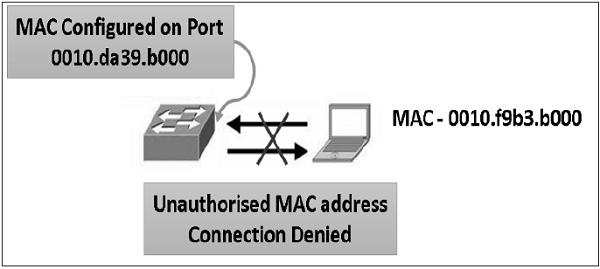
By default, port security limits the ingress MAC address count to one. However, it is possible to allow more than one authorized host to connect from that port through configuration. Allowed MAC addresses per interface can be statically configured. A convenient alternative is to enable "sticky" MAC address learning where MAC addresses will be dynamically learned by switch port until the maximum limit for the port is reached.
To ensure security, reaction to the change in the specified MAC address/es on a port or excess addresses on a port can be controlled in many different ways. The port can be configured to shut down or block the MAC addresses that exceed a specified limit. The recommended best practice is to shut down the port. Port security prevents MAC flooding and cloning attacks.
DHCP Snooping
We have seen that DHCP spoofing is an attack where the attacker listens for DHCP requests from host on the network and answers them with fake DHCP response before the authorized DHCP response comes to the host.
DHCP snooping can prevent such attacks. DHCP snooping is a switch feature. Switch can be configured to determine which switch ports can respond to DHCP requests. Switch ports are identified as trusted or untrusted ports.
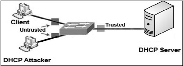
Only ports that connect to an authorized DHCP server are configured as “trusted”, and allowed to send all types of DHCP messages. All other ports on the switch are untrusted and can send only DHCP requests. If a DHCP response is seen on an untrusted port, the port is shut down.
Preventing ARP Spoofing
The method of port security can prevent MAC flooding and cloning attacks. However, it does not prevent ARP spoofing. Port security validates the MAC source address in the frame header, but ARP frames contain an additional MAC source field in the data payload, and the host uses this field to populate their ARP cache. Some methods to prevent ARP spoofing are listed as follows.
Static ARP − One of the recommended action is to employ static ARP entries in the host ARP table. Static ARP entries are permanent entries in an ARP cache. However, this method is impractical. Also, it does not allow the use of some Dynamic Host Configuration Protocol (DHCP) as static IP needs to be used for all host in the layer 2 network.
Intrusion Detection System − The method of defense is to utilize Intrusion Detection System (IDS) configured to detect high amounts of ARP traffic. However, IDS is prone to reporting false positives.
Dynamic ARP Inspection − This method of preventing ARP spoofing is similar to DHCP snooping. It uses trusted and untrusted ports. ARP replies are allowed into the switch interface only on trusted ports. If an ARP reply comes to the switch on an untrusted port, the contents of the ARP reply packet is compared to the DHCP binding table to verify its accuracy. If the ARP reply is not valid, the ARP reply is dropped, and the port is disabled.
Securing Spanning Tree Protocol
Spanning Tree Protocol (STP) is a layer 2 link management protocol. The main purpose of STP is to ensure that there are no data flow loops when network has redundant paths. Generally, redundant paths are built to provide reliability to the network. But they can form deadly loops which can lead to DoS attack in the network.
Spanning Tree Protocol
In order to provide desired path redundancy, as well as to avoid a loop condition, STP defines a tree that spans all the switches in a network. STP forces certain redundant data links into a blocked state and keeps other links in a forwarding state.
If a link in the forwarding state breaks down, STP reconfigures the network and redefines data paths by activating appropriate standby path. STP runs on bridges and switches deployed in the network. All the switches exchange information for root switch selection and for subsequent configuration of the network. Bridge Protocol Data Units (BPDUs) carry this information. Through exchange of BPDUs, all the switches in the network elect a root bridge/switch that becomes the focal point in the network and controls the blocked and forwarded links.
Attacks on STP
Taking Over the Root Bridge. It is one of the most disruptive type of attack at layer 2. By default, a LAN switch takes any BPDU sent from neighboring switch at face value. Incidentally, STP is trustful, stateless, and does not provide any sound authentication mechanism.
Once in root attack mode, the attacking switch sends a BPDU every 2 sec with the same priority as the current root bridge, but with a slightly numerically lower MAC address, which ensures its victory in the root-bridge election process. The attacker switch can launch DoS attack either by not properly acknowledging other switches causing BPDU flooding or by subjecting switches to over-process BPDUS by claiming to be root at one time and retracting in quick succession.
DoS using Flood of Configuration BPDU. The attacking switch does not attempt to take over as root. Instead, it generates large number of BPDUs per second leading to very high CPU utilization on the switches.
Preventing Attacks on STP
Fortunately, the countermeasure to a root takeover attack is simple and straightforward. Two features help in defeating a root takeover attack.
Root Guard − Root guard restricts the switch ports out of which the root bridge may be negotiated. If a ‘root-guard-enabled’ port receives BPDUs that are superior to those that the current root bridge is sending, then that port is moved to a root-inconsistent state, and no data traffic is forwarded across that port. Root guard is best deployed toward ports that connect to switches which are not expected to take over as the root bridge.
BPDU-Guard − BPDU guard is used to protect the network from the problems that may be caused by the receipt of BPDUs on access ports. These are the ports that should not be receiving them. BPDU guard is best deployed toward user-facing ports to prevent insertion of rogue switch by an attacker.
Securing Virtual LAN
In local networks, Virtual Local Area Networks (VLANs) are sometimes configured as a security measure to limit the number of hosts susceptible to layer 2 attacks. VLANs create network boundaries, over which broadcast (ARP, DHCP) traffic cannot cross.
Virtual Local Area Network
A network employing switch/es supporting VLAN capabilities can be configured to define multiple VLANs over a single physical LAN infrastructure.
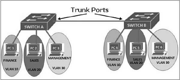
The common form of VLAN is a port-based VLAN. In this VLAN structure, the switch ports are grouped into VLAN using switch management software. Thus a single physical switch can act as multiple virtual switches.
Employment of VLANs provide traffic isolation. It divides the large broadcast layer 2 network into smaller logical layer 2 networks and thus reduces the scope of attacks such as ARP/DHCP Spoofing. Data frames of one VLAN can move from/to within ports belonging to the same VLAN only. The frames forwarding between two VLANs is done through routing.
VLANs generally span multiple switches as shown in the diagram above. The link between trunk ports carry frames of all VLANs defined over multiple physical switches. Hence, VLAN frames forwarded between switches can’t be simple IEEE 802.1 Ethernet format frames. Since, these frame move on same physical link, they now need to carry VLAN ID information. IEEE 802.1Q protocol adds/removes additional header fields to plain Ethernet frames forwarded between trunk ports.
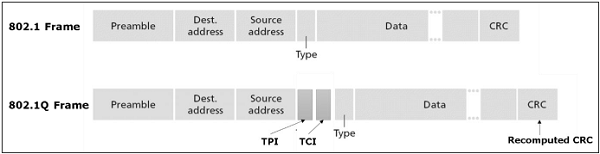
When the field following the two IP addresses fields is 0x8100 (> 1500), the frame is identified as 802.1Q frame. Value of 2-byte Tag Protocol Identifier (TPI) is 81-00. TCI field consist of 3-bit priority information, 1-bit Drop eligible indicator (DEI), and 12-bit VLAN ID. This 3-bit priority field and DEI field are not relevant to VLANs. Priority bits are used for provision of Quality of Service.
When a frame does not belong to any VLAN, there is a default VLAN id which the frame is considered to be associated with.
Attack on VLAN & Prevention Measures
In a VLAN hopping attack, an attacker on one VLAN can gain access to the traffic on other VLANs that would normally not be accessible. It would bypass a layer 3 device (router) when communicating from one VLAN to another, thus defeating the purpose of VLAN creation.
VLAN hopping can be performed by two methods; switch spoofing and double tagging.
Switch Spoofing
It can occur when the switch port, to which the attacker is connected, is either in ‘trunking’ mode or ‘auto-negotiation’ mode. The attacker acts as a switch and adds 802.1Q encapsulation headers with VLAN tags for target remote VLANs to its outgoing frames. The receiving switch interprets those frames as sourced from another 802.1Q switch, and forwards the frames into the target VLAN.
The two preventive measures against switch spoofing attacks are to set edge ports to static access mode and to disable auto-negotiation on all ports.
Double Tagging
In this attack, an attacker connected on native VLAN port of switch prepends two VLAN tags in the frame header. The first tag is of native VLAN and second is for target VLAN. When the first switch receives the attacker’s frames, it removes the first tag since frames of native VLAN are forwarded without tag on trunk port.
Since the second tag was never removed by the first switch, the receiving switch identifies the remaining tag as the VLAN destination and forwards the frames to the target host in that VLAN. The double tagging attack exploits the concept of native VLAN. Since VLAN 1 is the default VLAN for access ports and the default native VLAN on trunks, it’s an easy target.
The first prevention measure is to remove all access ports from the default VLAN 1 since the attacker’s port must match that of the switch’s native VLAN. The second prevention measure is to assign the native VLAN on all switch trunks to some unused VLAN, say VLAN id 999. And lastly, all switches be configured to carry out explicit tagging of native VLAN frames on the trunk port.
Securing Wireless LAN
Wireless local area network is a network of wireless nodes within a limited geographic area, such as an office building or school campus. Nodes are capable of radio communication.
Wireless LAN
Wireless LAN is usually implemented as extensions of existing wired LAN to provide network access with device mobility. The most widely implemented wireless LAN technologies are based on the IEEE 802.11 standard and its amendments.
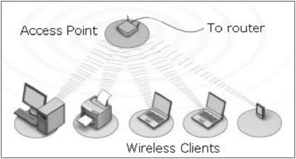
The two main components in wireless LAN are −
Access Points (APs) − These are base stations for the wireless network. They transmit and receive radio frequencies to communicate with wireless clients.
Wireless Clients − These are computing devices that are equipped with a Wireless Network Interface Card (WNIC). Laptops, IP Phones, PDAs are typical examples of wireless clients.
Many organizations have implemented wireless LANs. These networks are growing phenomenally. It is thus, crucial to understand threats in wireless LANs and learn the common preventive measure to ensure network security.
Attacks in Wireless LAN
The typical attacks that are carried out on Wireless LAN are −
Eavesdropping − The attacker passively monitors wireless networks for data, including authentication credentials.
Masquerading − The attacker impersonates an authorized user and gains access and privileges on wireless networks.
Traffic Analysis − The attacker monitors transmissions via wireless networks to identify communication patterns and participants.
Denial of Service − The attacker prevents or restricts the normal use or management of wireless LAN or network devices.
Message Modification/Replay − The attacker alters or replies to a legitimate message sent via wireless networks by deleting, adding to, changing, or reordering it.
Security Measures in Wireless LAN
Security measures provide means to defeat attacks and manage risks to the networks. These are network management, operation, and technical measures. We describe below the technical measures adopted to ensure confidentiality, availability, and integrity of data transmitted via wireless LANs.
In wireless LANs, all APs should be configured to provide security through encryption and client authentication. The types of schemes used in Wireless LAN to provide security are as follows −
Wired Equivalent Privacy (WEP)
It is an encryption algorithm built into the 802.11 standard to secure wireless networks. WEP encryption uses the RC4 (Rivest Cipher 4) stream cipher with 40-bit/104-bit keys and a 24-bit initialization vector. It can also provide endpoint authentication.
It is, however, the weakest encryption security mechanism, as a number of flaws have been discovered in WEP encryption. WEP also does not have authentication protocol. Hence, using WEP is not highly recommended.
802.11i Protocol
In this protocol numerous and stronger forms of encryption are possible. It has been developed to replace weak WEP scheme. It provides key distribution mechanism. It supports one key per station, and does not use the same key for all. It uses authentication server separate from the access point.
IEEE802.11i mandates the use of a protocol named Counter mode with CBC-MAC Protocol (CCMP). CCMP provides confidentiality and integrity of the data transferred and authenticity of the sender. It is based on the Advanced Encryption Standard (AES) block cipher.
The IEEE802.11i protocol has four phases of operation.
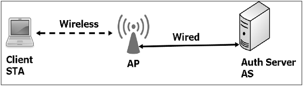
STA and AP communicate and discover mutual security capabilities such as supported algorithms.
STA and AS mutually authenticate and together generate Master Key (MK). AP acts as “pass through”.
STA derives Pairwise Master Key (PMK). AS derives same PMK and sends to AP.
STA, AP use PMK to derive Temporal Key (TK) to be used for message encryption and data integrity.
Other Standards
Wi-Fi Protected Access (WPA) − This protocol implements the majority of the IEEE 802.11i standard. It existed before IEEE 802.11i and uses RC4 algorithm for encryption. It has two modes of operation. In ‘Enterprise’ mode, WPA uses authentication protocol 802.1x to communicate with authentication server, and hence pre-master keys (PMK) is specific to client station. In ‘Personal’ mode, it does not use 802.1x, PMK is replaced by a pre-shared key, as used for Small Office Home Office (SOHO) wireless LAN environments.
WPA also includes a sound message integrity check replacing the Cyclic Redundancy Check (CRC) that was used by the WEP standard.
WPA2 − WPA2 replaced the WPA. WPA2 implements all mandatory elements of IEEE 802.11i scheme. In particular, it includes mandatory support for CCMP, an AES-based encryption mode with strong security. Thus, as far as the attacks are concerned, WPA2 / IEEE802.11i provides adequate solutions to defend against WEP weaknesses, man-in-the-middle attacks, forgery packets forgery, and replay attacks. However, DoS attack is not addressed properly and there are no solid protocols to stop such attacks basically because such attacks target the physical layer like interfering with the frequency band.
Summary
In this chapter, we considered attacks and mitigation techniques assuming a switched Ethernet network running IP. If your network does not use Ethernet as layer 2 protocol, some of these attacks may not be applicable, but chances are such network is vulnerable to different types of attacks.
Security is only as strong as the weakest link. When it comes to networking, layer 2 can be a very weak link. Layer 2 security measures mentioned in this chapter go a long way towards protecting a network from many types of attacks.