
- Microprocessor Tutorial
- Microprocessor - Home
- Microprocessor - Overview
- Microprocessor - Classification
- 8085 Microprocessor
- Microprocessor - 8085 Architecture
- 8085 Pin Configuration
- Addressing Modes & Interrupts
- 8085 Instruction Sets
- 8086 Microprocessor
- Microprocessor - 8086 Overview
- 8086 Functional Units
- 8086 Pin Configuration
- 8086 Instruction Sets
- Microprocessor - 8086 Interrupts
- 8086 Addressing Modes
- Multiprocessor Configuration
- Configuration Overview
- 8087 Numeric Data Processor
- I/O Interfacing
- I/O Interfacing Overview
- 8279 Programmable Keyboard
- 8257 DMA Controller
- Microcontrollers
- Microcontrollers - Overview
- Microcontrollers - 8051 Architecture
- 8051 Pin Description
- 8051 Input Output Ports
- Microcontrollers - 8051 Interrupts
- Peripheral Devices
- Programmable Peripheral Interface
- Intel 8255A - Pin Description
- 8253 - Programmable Interval Timer
- 8253/54 - Operational Modes
- Microprocessor Useful Resources
- Microprocessor - Quick Guide
- Microprocessor - Useful Resources
- Microprocessor - Discussion
Microprocessor - 8086 Interrupts
Interrupt is the method of creating a temporary halt during program execution and allows peripheral devices to access the microprocessor. The microprocessor responds to that interrupt with an ISR (Interrupt Service Routine), which is a short program to instruct the microprocessor on how to handle the interrupt.
The following image shows the types of interrupts we have in a 8086 microprocessor −
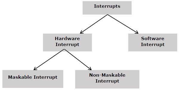
Hardware Interrupts
Hardware interrupt is caused by any peripheral device by sending a signal through a specified pin to the microprocessor.
The 8086 has two hardware interrupt pins, i.e. NMI and INTR. NMI is a non-maskable interrupt and INTR is a maskable interrupt having lower priority. One more interrupt pin associated is INTA called interrupt acknowledge.
NMI
It is a single non-maskable interrupt pin (NMI) having higher priority than the maskable interrupt request pin (INTR)and it is of type 2 interrupt.
When this interrupt is activated, these actions take place −
Completes the current instruction that is in progress.
Pushes the Flag register values on to the stack.
Pushes the CS (code segment) value and IP (instruction pointer) value of the return address on to the stack.
IP is loaded from the contents of the word location 00008H.
CS is loaded from the contents of the next word location 0000AH.
Interrupt flag and trap flag are reset to 0.
INTR
The INTR is a maskable interrupt because the microprocessor will be interrupted only if interrupts are enabled using set interrupt flag instruction. It should not be enabled using clear interrupt Flag instruction.
The INTR interrupt is activated by an I/O port. If the interrupt is enabled and NMI is disabled, then the microprocessor first completes the current execution and sends ‘0’ on INTA pin twice. The first ‘0’ means INTA informs the external device to get ready and during the second ‘0’ the microprocessor receives the 8 bit, say X, from the programmable interrupt controller.
These actions are taken by the microprocessor −
First completes the current instruction.
Activates INTA output and receives the interrupt type, say X.
Flag register value, CS value of the return address and IP value of the return address are pushed on to the stack.
IP value is loaded from the contents of word location X × 4
CS is loaded from the contents of the next word location.
Interrupt flag and trap flag is reset to 0
Software Interrupts
Some instructions are inserted at the desired position into the program to create interrupts. These interrupt instructions can be used to test the working of various interrupt handlers. It includes −
INT- Interrupt instruction with type number
It is 2-byte instruction. First byte provides the op-code and the second byte provides the interrupt type number. There are 256 interrupt types under this group.
Its execution includes the following steps −
Flag register value is pushed on to the stack.
CS value of the return address and IP value of the return address are pushed on to the stack.
IP is loaded from the contents of the word location ‘type number’ × 4
CS is loaded from the contents of the next word location.
Interrupt Flag and Trap Flag are reset to 0
The starting address for type0 interrupt is 000000H, for type1 interrupt is 00004H similarly for type2 is 00008H and ……so on. The first five pointers are dedicated interrupt pointers. i.e. −
TYPE 0 interrupt represents division by zero situation.
TYPE 1 interrupt represents single-step execution during the debugging of a program.
TYPE 2 interrupt represents non-maskable NMI interrupt.
TYPE 3 interrupt represents break-point interrupt.
TYPE 4 interrupt represents overflow interrupt.
The interrupts from Type 5 to Type 31 are reserved for other advanced microprocessors, and interrupts from 32 to Type 255 are available for hardware and software interrupts.
INT 3-Break Point Interrupt Instruction
It is a 1-byte instruction having op-code is CCH. These instructions are inserted into the program so that when the processor reaches there, then it stops the normal execution of program and follows the break-point procedure.
Its execution includes the following steps −
Flag register value is pushed on to the stack.
CS value of the return address and IP value of the return address are pushed on to the stack.
IP is loaded from the contents of the word location 3×4 = 0000CH
CS is loaded from the contents of the next word location.
Interrupt Flag and Trap Flag are reset to 0
INTO - Interrupt on overflow instruction
It is a 1-byte instruction and their mnemonic INTO. The op-code for this instruction is CEH. As the name suggests it is a conditional interrupt instruction, i.e. it is active only when the overflow flag is set to 1 and branches to the interrupt handler whose interrupt type number is 4. If the overflow flag is reset then, the execution continues to the next instruction.
Its execution includes the following steps −
Flag register values are pushed on to the stack.
CS value of the return address and IP value of the return address are pushed on to the stack.
IP is loaded from the contents of word location 4×4 = 00010H
CS is loaded from the contents of the next word location.
Interrupt flag and Trap flag are reset to 0