- MATLAB Simulink Tutorial
- MATLAB Simulink - Home
- MATLAB Simulink - Introduction
- MATLAB Simulink - Environment Setup
- MATLAB Simulink - Starting Simulink
- MATLAB Simulink - Blocks
- MATLAB Simulink - Lines
- MATLAB Simulink - Build & Simulate Model
- MATLAB Simulink - Signals Processing
- MATLAB Simulink - Adding Delay To Signals
- MATLAB Simulink - Mathematical Library
- Build Model & Apply If-else Logic
- MATLAB Simulink - Logic Gates Model
- MATLAB Simulink - Sinewave
- MATLAB Simulink - Function
- MATLAB Simulink - Create Subsystem
- MATLAB Simulink - For Loop
- MATLAB Simulink - Export Data
- MATLAB Simulink - Script
- Solving Mathematical Equation
- First Order Differential Equation
- MATLAB Simulink Useful Resources
- MATLAB Simulink - Quick Guide
- MATLAB Simulink - Useful Resources
- MATLAB Simulink - Discussion
MATLAB Simulink - Signals Processing
In this chapter, we will understand the signals generation in Simulink. To start with, select a blank model from Simulink page and open Simulink browser library as shown below −
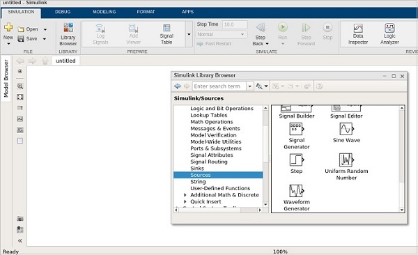
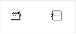
In sources library, you will get a signal generator symbol. It will help us to create different types of signals.
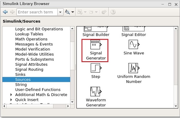
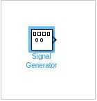
Select the Signal Generator and drag it to get inside the blank model as shown below −
To see the output of the signal generator, we need one more block called scope from sinks library as shown below −
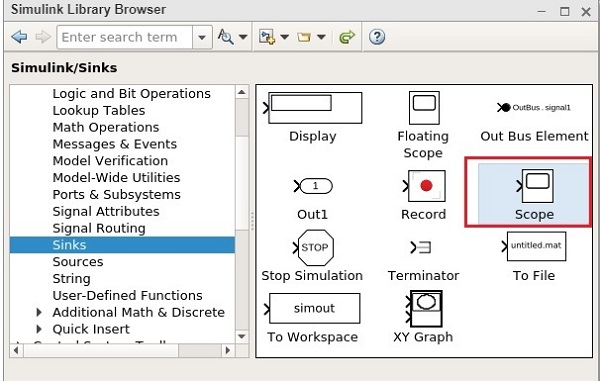
Select the block and drag it to get inside the model.
Double click on signal generator or right click and select block parameters and it will display a screen as shown below −
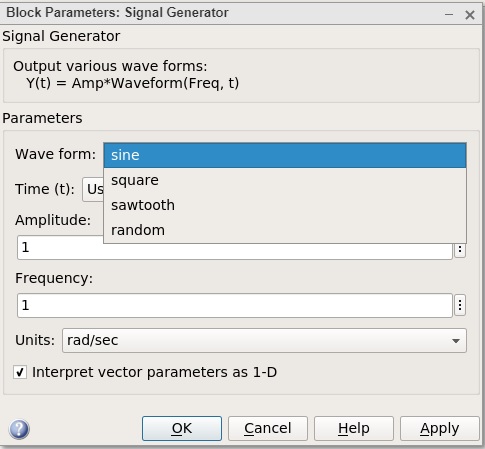
The signal generator can show waveforms like sine, square, sawtooth, random. We will select the square waveform. Let the amplitude and frequency be as 1. Click on OK to update the changes made.
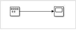
Now, connect the lines between signal generator and scope block as shown below −
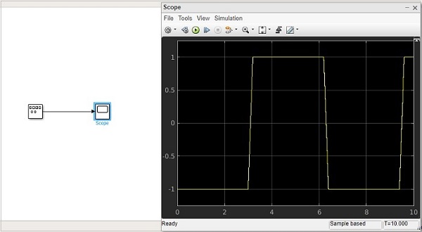
Now click on Run button to see the square waveform as shown below −
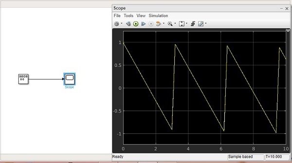
Let us now try the sawtooth wave form. Right click signal generator or double click and change the waveform to sawtooth.
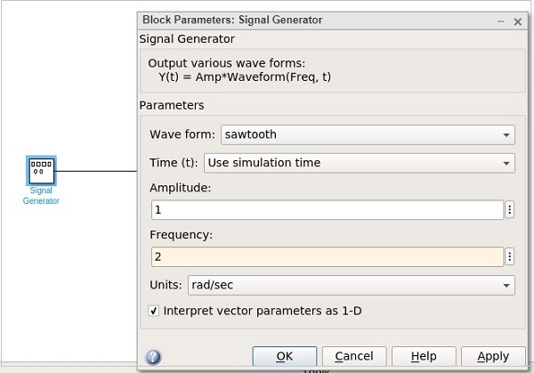
Let us change the frequency to 2. Click on OK to update the changes. Now run the model to see the changes as shown below −
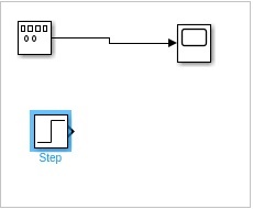
Let us now add some more signals to the above model. We will take the step signal from the sources library as shown below −
We just have one input for the scope block. Let us increase it to 2 inputs. Right click and open the block parameters.
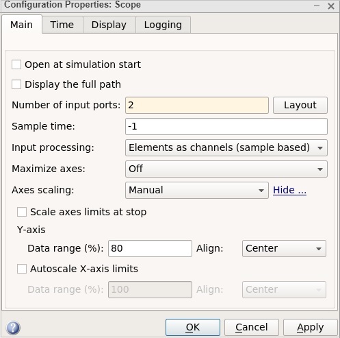
Click on OK button to update the changes. Now, the scope block has 2 inputs as shown below −
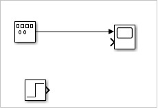
Connect the step input arrow with the scope arrow.
Now click on Run button to run the model.
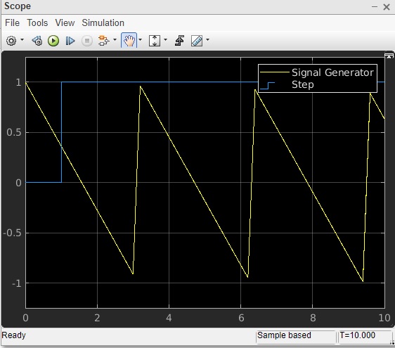
You can add some more signals and test the same.