- LTE Tutorial
- LTE - Home
- LTE - Overview
- LTE - Basic Parameters
- LTE - Network Architecture
- LTE - Roaming Architecture
- LTE - Numbering & Addressing
- LTE - Radio Protocol Architecture
- LTE - Protocol Stack Layers
- LTE - Layers Data Flow
- LTE - Communication Channels
- LTE - OFDM Technology
- LTE - Glossary
- LTE Useful Resources
- LTE - Quick Guide
- LTE - Useful Resources
- LTE - Discussion
LTE Quick Guide
LTE Overview
LTE stands for Long Term Evolution and it was started as a project in 2004 by telecommunication body known as the Third Generation Partnership Project (3GPP). SAE (System Architecture Evolution) is the corresponding evolution of the GPRS/3G packet core network evolution. The term LTE is typically used to represent both LTE and SAE.
LTE evolved from an earlier 3GPP system known as the Universal Mobile Telecommunication System (UMTS), which in turn evolved from the Global System for Mobile Communications (GSM). Even related specifications were formally known as the evolved UMTS terrestrial radio access (E-UTRA) and evolved UMTS terrestrial radio access network (E-UTRAN). First version of LTE was documented in Release 8 of the 3GPP specifications.
A rapid increase of mobile data usage and emergence of new applications such as MMOG (Multimedia Online Gaming), mobile TV, Web 2.0, streaming contents have motivated the 3rd Generation Partnership Project (3GPP) to work on the Long-Term Evolution (LTE) on the way towards fourth-generation mobile.
The main goal of LTE is to provide a high data rate, low latency and packet optimized radioaccess technology supporting flexible bandwidth deployments. Same time its network architecture has been designed with the goal to support packet-switched traffic with seamless mobility and great quality of service.
LTE Evolution
| Year | Event |
|---|---|
| Mar 2000 | Release 99 - UMTS/WCDMA |
| Mar 2002 | Rel 5 - HSDPA |
| Mar 2005 | Rel 6 - HSUPA |
| Year 2007 | Rel 7 - DL MIMO, IMS (IP Multimedia Subsystem) |
| November 2004 | Work started on LTE specification |
| January 2008 | Spec finalized and approved with Release 8 |
| 2010 | Targeted first deployment |
Facts about LTE
LTE is the successor technology not only of UMTS but also of CDMA 2000.
LTE is important because it will bring up to 50 times performance improvement and much better spectral efficiency to cellular networks.
LTE introduced to get higher data rates, 300Mbps peak downlink and 75 Mbps peak uplink. In a 20MHz carrier, data rates beyond 300Mbps can be achieved under very good signal conditions.
LTE is an ideal technology to support high date rates for the services such as voice over IP (VOIP), streaming multimedia, videoconferencing or even a high-speed cellular modem.
LTE uses both Time Division Duplex (TDD) and Frequency Division Duplex (FDD) mode. In FDD uplink and downlink transmission used different frequency, while in TDD both uplink and downlink use the same carrier and are separated in Time.
LTE supports flexible carrier bandwidths, from 1.4 MHz up to 20 MHz as well as both FDD and TDD. LTE designed with a scalable carrier bandwidth from 1.4 MHz up to 20 MHz which bandwidth is used depends on the frequency band and the amount of spectrum available with a network operator.
All LTE devices have to support (MIMO) Multiple Input Multiple Output transmissions, which allow the base station to transmit several data streams over the same carrier simultaneously.
All interfaces between network nodes in LTE are now IP based, including the backhaul connection to the radio base stations. This is great simplification compared to earlier technologies that were initially based on E1/T1, ATM and frame relay links, with most of them being narrowband and expensive.
Quality of Service (QoS) mechanism have been standardized on all interfaces to ensure that the requirement of voice calls for a constant delay and bandwidth, can still be met when capacity limits are reached.
Works with GSM/EDGE/UMTS systems utilizing existing 2G and 3G spectrum and new spectrum. Supports hand-over and roaming to existing mobile networks.
Advantages of LTE
High throughput: High data rates can be achieved in both downlink as well as uplink. This causes high throughput.
Low latency: Time required to connect to the network is in range of a few hundred milliseconds and power saving states can now be entered and exited very quickly.
FDD and TDD in the same platform: Frequency Division Duplex (FDD) and Time Division Duplex (TDD), both schemes can be used on same platform.
Superior end-user experience: Optimized signaling for connection establishment and other air interface and mobility management procedures have further improved the user experience. Reduced latency (to 10 ms) for better user experience.
Seamless Connection: LTE will also support seamless connection to existing networks such as GSM, CDMA and WCDMA.
Plug and play: The user does not have to manually install drivers for the device. Instead system automatically recognizes the device, loads new drivers for the hardware if needed, and begins to work with the newly connected device.
Simple architecture: Because of Simple architecture low operating expenditure (OPEX).
LTE - QoS
LTE architecture supports hard QoS, with end-to-end quality of service and guaranteed bit rate (GBR) for radio bearers. Just as Ethernet and the internet have different types of QoS, for example, various levels of QoS can be applied to LTE traffic for different applications. Because the LTE MAC is fully scheduled, QoS is a natural fit.
Evolved Packet System (EPS) bearers provide one-to-one correspondence with RLC radio bearers and provide support for Traffic Flow Templates (TFT). There are four types of EPS bearers:
GBR Bearer resources permanently allocated by admission control
Non-GBR Bearer no admission control
Dedicated Bearer associated with specific TFT (GBR or non-GBR)
Default Bearer Non GBR, catch-all for unassigned traffic
LTE Basic Parameters
This section will summarize the Basic parameters of the LTE:
| Parameters | Description |
|---|---|
| Frequency range | UMTS FDD bands and TDD bands defined in 36.101(v860) Table 5.5.1, given below |
| Duplexing | FDD, TDD, half-duplex FDD |
| Channel coding | Turbo code |
| Mobility | 350 km/h |
| Channel Bandwidth (MHz) |
|
| Transmission Bandwidth Configuration NRB : (1 resource block = 180kHz in 1ms TTI ) |
|
| Modulation Schemes | UL: QPSK, 16QAM, 64QAM(optional) DL: QPSK, 16QAM, 64QAM |
| Multiple Access Schemes | UL: SC-FDMA (Single Carrier Frequency Division Multiple Access) supports 50Mbps+ (20MHz spectrum) DL: OFDM (Orthogonal Frequency Division Multiple Access) supports 100Mbps+ (20MHz spectrum) |
| Multi-Antenna Technology | UL: Multi-user collaborative MIMO DL: TxAA, spatial multiplexing, CDD ,max 4x4 array |
| Peak data rate in LTE | UL: 75Mbps(20MHz bandwidth) DL: 150Mbps(UE Category 4, 2x2 MIMO, 20MHz bandwidth) DL: 300Mbps(UE category 5, 4x4 MIMO, 20MHz bandwidth) |
MIMO (Multiple Input Multiple Output) |
UL: 1 x 2, 1 x 4 DL: 2 x 2, 4 x 2, 4 x 4 |
| Coverage | 5 - 100km with slight degradation after 30km |
| QoS | E2E QOS allowing prioritization of different class of service |
| Latency | End-user latency < 10mS |
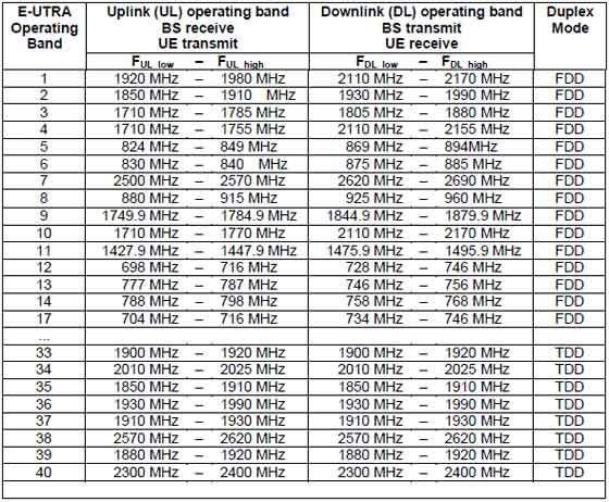
E-UTRA Operating Bands
Following is the table for E-UTRA operating bands taken from LTE Sepecification 36.101(v860) Table 5.5.1:
LTE Network Architecture
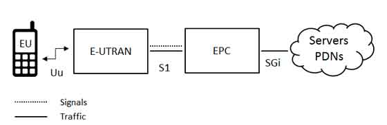
The high-level network architecture of LTE is comprised of following three main components:
The User Equipment (UE).
The Evolved UMTS Terrestrial Radio Access Network (E-UTRAN).
The Evolved Packet Core (EPC).
The evolved packet core communicates with packet data networks in the outside world such as the internet, private corporate networks or the IP multimedia subsystem. The interfaces between the different parts of the system are denoted Uu, S1 and SGi as shown below:
The User Equipment (UE)
The internal architecture of the user equipment for LTE is identical to the one used by UMTS and GSM which is actually a Mobile Equipment (ME). The mobile equipment comprised of the following important modules:
Mobile Termination (MT) : This handles all the communication functions.
Terminal Equipment (TE) : This terminates the data streams.
Universal Integrated Circuit Card (UICC) : This is also known as the SIM card for LTE equipments. It runs an application known as the Universal Subscriber Identity Module (USIM).
A USIM stores user-specific data very similar to 3G SIM card. This keeps information about the user's phone number, home network identity and security keys etc.
The E-UTRAN (The access network)
The architecture of evolved UMTS Terrestrial Radio Access Network (E-UTRAN) has been illustrated below.
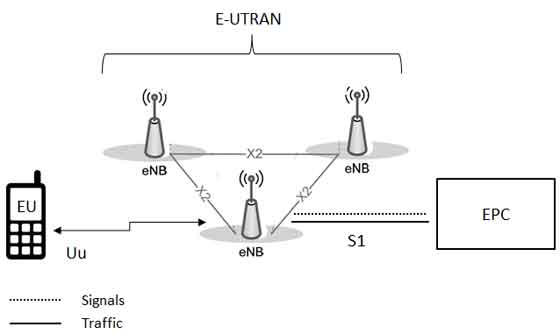
The E-UTRAN handles the radio communications between the mobile and the evolved packet core and just has one component, the evolved base stations, called eNodeB or eNB. Each eNB is a base station that controls the mobiles in one or more cells. The base station that is communicating with a mobile is known as its serving eNB.
LTE Mobile communicates with just one base station and one cell at a time and there are following two main functions supported by eNB:
The eNB sends and receives radio transmissions to all the mobiles using the analogue and digital signal processing functions of the LTE air interface.
The eNB controls the low-level operation of all its mobiles, by sending them signalling messages such as handover commands.
Each eNB connects with the EPC by means of the S1 interface and it can also be connected to nearby base stations by the X2 interface, which is mainly used for signalling and packet forwarding during handover.
A home eNB (HeNB) is a base station that has been purchased by a user to provide femtocell coverage within the home. A home eNB belongs to a closed subscriber group (CSG) and can only be accessed by mobiles with a USIM that also belongs to the closed subscriber group.
The Evolved Packet Core (EPC) (The core network)
The architecture of Evolved Packet Core (EPC) has been illustrated below. There are few more components which have not been shown in the diagram to keep it simple. These components are like the Earthquake and Tsunami Warning System (ETWS), the Equipment Identity Register (EIR) and Policy Control and Charging Rules Function (PCRF).
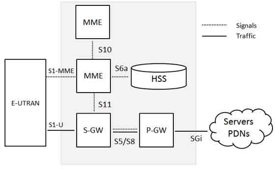
Below is a brief description of each of the components shown in the above architecture:
The Home Subscriber Server (HSS) component has been carried forward from UMTS and GSM and is a central database that contains information about all the network operator's subscribers.
The Packet Data Network (PDN) Gateway (P-GW) communicates with the outside world ie. packet data networks PDN, using SGi interface. Each packet data network is identified by an access point name (APN). The PDN gateway has the same role as the GPRS support node (GGSN) and the serving GPRS support node (SGSN) with UMTS and GSM.
The serving gateway (S-GW) acts as a router, and forwards data between the base station and the PDN gateway.
The mobility management entity (MME) controls the high-level operation of the mobile by means of signalling messages and Home Subscriber Server (HSS).
The Policy Control and Charging Rules Function (PCRF) is a component which is not shown in the above diagram but it is responsible for policy control decision-making, as well as for controlling the flow-based charging functionalities in the Policy Control Enforcement Function (PCEF), which resides in the P-GW.
The interface between the serving and PDN gateways is known as S5/S8. This has two slightly different implementations, namely S5 if the two devices are in the same network, and S8 if they are in different networks.
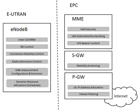
Functional split between the E-UTRAN and the EPC
Following diagram shows the functional split between the E-UTRAN and the EPC for an LTE network:
2G/3G Versus LTE
Following table compares various important Network Elements & Signaling protocols used in 2G/3G abd LTE.
| 2G/3G | LTE |
|---|---|
| GERAN and UTRAN | E-UTRAN |
| SGSN/PDSN-FA | S-GW |
| GGSN/PDSN-HA | PDN-GW |
| HLR/AAA | HSS |
| VLR | MME |
| SS7-MAP/ANSI-41/RADIUS | Diameter |
| DiameterGTPc-v0 and v1 | GTPc-v2 |
| MIP | PMIP |
LTE Roaming Architecture
A network run by one operator in one country is known as a Public Land Mobile Network (PLMN) and when a subscribed user uses his operator's PLMN then it is said Home-PLMN but roaming allows users to move outside their home network and using the resources from other operator's network. This other network is called Visited-PLMN.
A roaming user is connected to the E-UTRAN, MME and S-GW of the visited LTE network. However, LTE/SAE allows the P-GW of either the visited or the home network to be used, as shown in below:
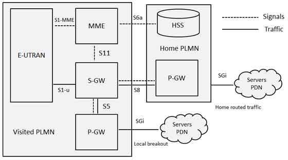
The home network's P-GW allows the user to access the home operator's services even while in a visited network. A P-GW in the visited network allows a "local breakout" to the Internet in the visited network.
The interface between the serving and PDN gateways is known as S5/S8. This has two slightly different implementations, namely S5 if the two devices are in the same network, and S8 if they are in different networks. For mobiles that are not roaming, the serving and PDN gateways can be integrated into a single device, so that the S5/S8 interface vanishes altogether.
LTE Roaming Charging
The complexities of the new charging mechanisms required to support 4G roaming are much more abundant than in a 3G environment. Few words about both pre-paid and post-paid charging for LTE roaming is given below:
Prepaid Charging - The CAMEL standard, which enables prepaid services in 3G, is not supported in LTE; therefore, prepaid customer information must be routed back to the home network as opposed to being handled by the local visited network. As a result, operators must rely on new accounting flows to access prepaid customer data, such as through their P-Gateways in both IMS and non-IMS environments or via their CSCF in an IMS environment.
Postpaid Charging - Postpaid data-usage charging works the same in LTE as it does in 3G, using versions TAP 3.11 or 3.12. With local breakout of IMS services, TAP 3.12 is required.
Operators do not have the same amount of visibility into subscriber activities as they do in home-routing scenarios in case of local breakout scenarios because subscriber-data sessions are kept within the visited network; therefore, in order for the home operator to capture real-time information on both pre- and postpaid customers, it must establish a Diameter interface between charging systems and the visited network's P-Gateway.
In case of local breakout of ims services scenario, the visited network creates call detail records (CDRs) from the S-Gateway(s), however, these CDRs do not contain all of the information required to create a TAP 3.12 mobile session or messaging event record for the service usage. As a result, operators must correlate the core data network CDRs with the IMS CDRs to create TAP records.
LTE Numbering & Addressing
An LTE network area is divided into three different types of geographical areas explained below:
| S.N. | Area and Description |
|---|---|
| 1 | The MME pool areas This is an area through which the mobile can move without a change of serving MME. Every MME pool area is controlled by one or more MMEs on the network. |
| 2 | The S-GW service areas This is an area served by one or more serving gateways S-GW, through which the mobile can move without a change of serving gateway. |
| 3 | The Tracking areas The MME pool areas and the S-GW service areas are both made from smaller, non-overlapping units known as tracking areas (TAs). They are similar to the location and routing areas from UMTS and GSM and will be used to track the locations of mobiles that are on standby mode. |
Thus an LTE network will comprise of many MME pool areas, many S-GW service areas and lots of tracking areas.
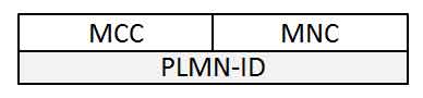
The Network IDs
The network itself will be identified using Public Land Mobile Network Identity (PLMN-ID) which will have a three digit mobile country code (MCC) and a two or three digit mobile network code (MNC). For example, the Mobile Country Code for the UK is 234, while Vodafone's UK network uses a Mobile Network Code of 15.
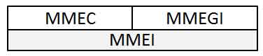
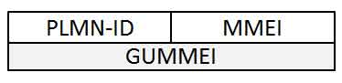
The MME IDs
Each MME has three main identities. An MME code (MMEC) uniquely identifies the MME within all the pool areas. A group of MMEs is assigned an MME Group Identity (MMEGI) which works along with MMEC to make MME identifier (MMEI). A MMEI uniquely identifies the MME within a particular network.
If we combile PLMN-ID with the MMEI then we arrive at a Globally Unique MME Identifier (GUMMEI), which identifies an MME anywhere in the world:
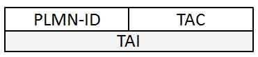
The Tracking Area IDs
Each tracking area has two main identities. The tracking area code (TAC) identifies a tracking area within a particular network and if we combining this with the PLMN-ID then we arrive at a Globally Unique Tracking Area Identity (TAI).
The Cell IDs
Each cell in the network has three types of identity. The E-UTRAN cell identity (ECI) identifies a cell within a particular network, while the E-UTRAN cell global identifier (ECGI) identifies a cell anywhere in the world.
The physical cell identity, which is a number from 0 to 503 and it distinguishes a cell from its immediate neighbours.
The Mobile Equipment ID
The international mobile equipment identity (IMEI) is a unique identity for the mobile equipment and the International Mobile Subscriber Identity (IMSI) is a unique identity for the UICC and the USIM.
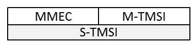
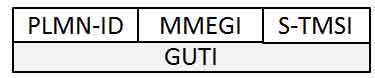
The M temporary mobile subscriber identity (M-TMSI) identifies a mobile to its serving MME. Adding the MME code in M-TMSI results in a S temporary mobile subscriber identity (S-TMSI), which identifies the mobile within an MME pool area.
Finally adding the MME group identity and the PLMN identity with S-TMSI results in the Globally Unique Temporary Identity (GUTI).
LTE Radio Protocol Architecture
The radio protocol architecture for LTE can be separated into control plane architecture and user plane architecture as shown below:
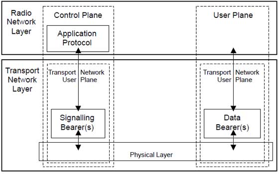
At user plane side, the application creates data packets that are processed by protocols such as TCP, UDP and IP, while in the control plane, the radio resource control (RRC) protocol writes the signalling messages that are exchanged between the base station and the mobile. In both cases, the information is processed by the packet data convergence protocol (PDCP), the radio link control (RLC) protocol and the medium access control (MAC) protocol, before being passed to the physical layer for transmission.
User Plane
The user plane protocol stack between the e-Node B and UE consists of the following sub-layers:
PDCP (Packet Data Convergence Protocol)
RLC (radio Link Control)
Medium Access Control (MAC)
On the user plane, packets in the core network (EPC) are encapsulated in a specific EPC protocol and tunneled between the P-GW and the eNodeB. Different tunneling protocols are used depending on the interface. GPRS Tunneling Protocol (GTP) is used on the S1 interface between the eNodeB and S-GW and on the S5/S8 interface between the S-GW and P-GW.
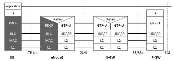
Packets received by a layer are called Service Data Unit (SDU) while the packet output of a layer is referred to by Protocol Data Unit (PDU) and IP packets at user plane flow from top to bottom layers.
Control Plane
The control plane includes additionally the Radio Resource Control layer (RRC) which is responsible for configuring the lower layers.
The Control Plane handles radio-specific functionality which depends on the state of the user equipment which includes two states: idle or connected.
| Mode | Description |
|---|---|
| Idle | The user equipment camps on a cell after a cell selection or reselection process where factors like radio link quality, cell status and radio access technology are considered. The UE also monitors a paging channel to detect incoming calls and acquire system information. In this mode, control plane protocols include cell selection and reselection procedures. |
| Connected | The UE supplies the E-UTRAN with downlink channel quality and neighbour cell information to enable the E-UTRAN to select the most suitable cell for the UE. In this case, control plane protocol includes the Radio Link Control (RRC) protocol. |
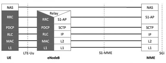
The protocol stack for the control plane between the UE and MME is shown below. The grey region of the stack indicates the access stratum (AS) protocols. The lower layers perform the same functions as for the user plane with the exception that there is no header compression function for the control plane.
LTE Protocol Stack Layers
Let's have a close look at all the layers available in E-UTRAN Protocol Stack which we have seen in previous chapter. Below is a more ellaborated diagram of E-UTRAN Protocol Stack:
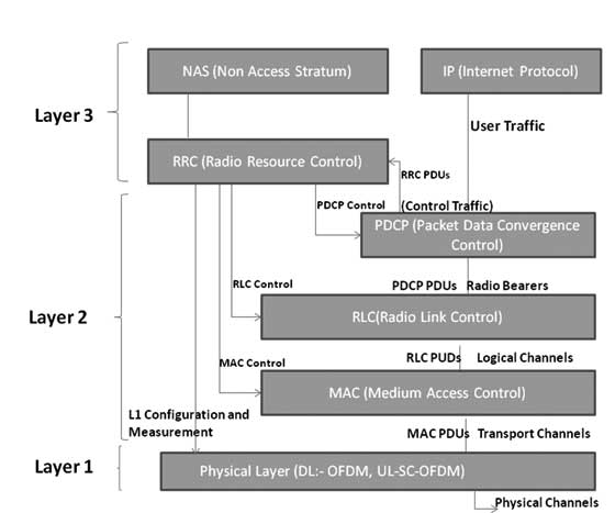
Physical Layer (Layer 1)
Physical Layer carries all information from the MAC transport channels over the air interface. Takes care of the link adaptation (AMC), power control, cell search (for initial synchronization and handover purposes) and other measurements (inside the LTE system and between systems) for the RRC layer.
Medium Access Layer (MAC)
MAC layer is responsible for Mapping between logical channels and transport channels, Multiplexing of MAC SDUs from one or different logical channels onto transport blocks (TB) to be delivered to the physical layer on transport channels, de multiplexing of MAC SDUs from one or different logical channels from transport blocks (TB) delivered from the physical layer on transport channels, Scheduling information reporting, Error correction through HARQ, Priority handling between UEs by means of dynamic scheduling, Priority handling between logical channels of one UE, Logical Channel prioritization.
Radio Link Control (RLC)
RLC operates in 3 modes of operation: Transparent Mode (TM), Unacknowledged Mode (UM), and Acknowledged Mode (AM).
RLC Layer is responsible for transfer of upper layer PDUs, error correction through ARQ (Only for AM data transfer), Concatenation, segmentation and reassembly of RLC SDUs (Only for UM and AM data transfer).
RLC is also responsible for re-segmentation of RLC data PDUs (Only for AM data transfer), reordering of RLC data PDUs (Only for UM and AM data transfer), duplicate detection (Only for UM and AM data transfer), RLC SDU discard (Only for UM and AM data transfer), RLC re-establishment, and protocol error detection (Only for AM data transfer).
Radio Resource Control (RRC)
The main services and functions of the RRC sublayer include broadcast of System Information related to the non-access stratum (NAS), broadcast of System Information related to the access stratum (AS), Paging, establishment, maintenance and release of an RRC connection between the UE and E-UTRAN, Security functions including key management, establishment, configuration, maintenance and release of point to point Radio Bearers.
Packet Data Convergence Control (PDCP)
PDCP Layer is responsible for Header compression and decompression of IP data, Transfer of data (user plane or control plane), Maintenance of PDCP Sequence Numbers (SNs), In-sequence delivery of upper layer PDUs at re-establishment of lower layers, Duplicate elimination of lower layer SDUs at re-establishment of lower layers for radio bearers mapped on RLC AM, Ciphering and deciphering of user plane data and control plane data, Integrity protection and integrity verification of control plane data, Timer based discard, duplicate discarding, PDCP is used for SRBs and DRBs mapped on DCCH and DTCH type of logical channels.
Non Access Stratum (NAS) Protocols
The non-access stratum (NAS) protocols form the highest stratum of the control plane between the user equipment (UE) and MME.
NAS protocols support the mobility of the UE and the session management procedures to establish and maintain IP connectivity between the UE and a PDN GW.
LTE Layers Data Flow
Below is a logical digram of E-UTRAN Protocol layers with a depiction of data flow through various layers:
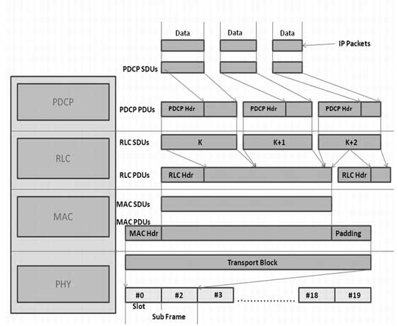
Packets received by a layer are called Service Data Unit (SDU) while the packet output of a layer is referred to by Protocol Data Unit (PDU). Let's see the flow of data from top to bottom:
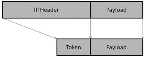
IP Layer submits PDCP SDUs (IP Packets) to the PDCP layer. PDCP layer does header compression and adds PDCP header to these PDCP SDUs. PDCP Layer submits PDCP PDUs (RLC SDUs) to RLC layer.
PDCP Header Compression : PDCP removes IP header (Minimum 20 bytes) from PDU, and adds Token of 1-4 bytes. Which provides a tremendous savings in the amount of header that would otherwise have to go over the air.
RLC layer does segmentation of these SDUS to make the RLC PDUs. RLC adds header based on RLC mode of operation. RLC submits these RLC PDUs (MAC SDUs) to the MAC layer.
RLC Segmentation : If an RLC SDU is large, or the available radio data rate is low (resulting in small transport blocks), the RLC SDU may be split among several RLC PDUs. If the RLC SDU is small, or the available radio data rate is high, several RLC SDUs may be packed into a single PDU.
MAC layer adds header and does padding to fit this MAC SDU in TTI. MAC layer submits MAC PDU to physical layer for transmitting it onto physical channels.
Physical channel transmits this data into slots of sub frame.
LTE Communication Channels
The information flows between the different protocols are known as channels and signals. LTE uses several different types of logical, transport and physical channel, which are distinguished by the kind of information they carry and by the way in which the information is processed.
Logical Channels : Define whattype of information is transmitted over the air, e.g. traffic channels, control channels, system broadcast, etc. Data and signalling messages are carried on logical channels between the RLC and MAC protocols.
Transport Channels : Define howis something transmitted over the air, e.g. what are encoding, interleaving options used to transmit data. Data and signalling messages are carried on transport channels between the MAC and the physical layer.
Physical Channels : Define whereis something transmitted over the air, e.g. first N symbols in the DL frame. Data and signalling messages are carried on physical channels between the different levels of the physical layer.
Logical Channels
Logical channels define what type of data is transferred. These channels define the data-transfer services offered by the MAC layer. Data and signalling messages are carried on logical channels between the RLC and MAC protocols.
Logical channels can be divided into control channels and traffic channels. Control Channel can be either common channel or dedicated channel. A common channel means common to all users in a cell (Point to multipoint) while dedicated channels means channels can be used only by one user (Point to Point).
Logical channels are distinguished by the information they carry and can be classified in two ways. Firstly, logical traffic channels carry data in the user plane, while logical control channels carry signalling messages in the control plane. Following table lists the logical channels that are used by LTE:
| Channel Name | Acronym | Control channel | Traffic channel |
|---|---|---|---|
| Broadcast Control Channel | BCCH | X | |
| Paging Control Channel | PCCH | X | |
| Common Control Channel | CCCH | X | |
| Dedicated Control Channel | DCCH | X | |
| Multicast Control Channel | MCCH | X | |
| Dedicated Traffic Channel | DTCH | X | |
| Multicast Traffic Channel | MTCH | X |
Transport Channels
Transport channels define how and with what type of characteristics the data is transferred by the physical layer. Data and signalling messages are carried on transport channels between the MAC and the physical layer.
Transport Channels are distinguished by the ways in which the transport channel processor manipulates them. Following table lists the transport channels that are used by LTE:
| Channel Name | Acronym | Downlink | Uplink |
|---|---|---|---|
| Broadcast Channel | BCH | X | |
| Downlink Shared Channel | DL-SCH | X | |
| Paging Channel | PCH | X | |
| Multicast Channel | MCH | X | |
| Uplink Shared Channel | UL-SCH | X | |
| Random Access Channel | RACH | X |
Physical Channels
Data and signalling messages are carried on physical channels between the different levels of the physical layer and accordingly they are divided into two parts:
Physical Data Channels
Physical Control Channels
Physical data channels
Physical data channels are distinguished by the ways in which the physical channel processor manipulates them, and by the ways in which they are mapped onto the symbols and sub-carriers used by Orthogonal frequency-division multiplexing (OFDMA). Following table lists the physical data channels that are used by LTE:
| Channel Name | Acronym | Downlink | Uplink |
|---|---|---|---|
| Physical downlink shared channel | PDSCH | X | |
| Physical broadcast channel | PBCH | X | |
| Physical multicast channel | PMCH | X | |
| Physical uplink shared channel | PUSCH | X | |
| Physical random access channel | PRACH | X |
The transport channel processor composes several types of control information, to support the low-level operation of the physical layer. These are listed in the below table:
| Field Name | Acronym | Downlink | Uplink |
|---|---|---|---|
| Downlink control information | DCI | X | |
| Control format indicator | CFI | X | |
| Hybrid ARQ indicator | HI | X | |
| Uplink control information | UCI | X |
Physical Control Channels
The transport channel processor also creates control information that supports the low-level operation of the physical layer and sends this information to the physical channel processor in the form of physical control channels.
The information travels as far as the transport channel processor in the receiver, but is completely invisible to higher layers. Similarly, the physical channel processor creates physical signals, which support the lowest-level aspects of the system.
Physical Control Channels are listed in the below table:
| Channel Name | Acronym | Downlink | Uplink |
|---|---|---|---|
| Physical control format indicator channel | PCFICH | X | |
| Physical hybrid ARQ indicator channel | PHICH | X | |
| Physical downlink control channel | PDCCH | X | |
| Relay physical downlink control channel | R-PDCCH | X | |
| Physical uplink control channel | PUCCH | X |
The base station also transmits two other physical signals, which help the mobile acquire the base station after it first switches on. These are known as the primary synchronization signal (PSS) and the secondary synchronization signal (SSS).
LTE OFDM Technology
To overcome the effect of multi path fading problem available in UMTS, LTE uses Orthogonal Frequency Division Multiplexing (OFDM) for the downlink - that is, from the base station to the terminal to transmit the data over many narrow band careers of 180 KHz each instead of spreading one signal over the complete 5MHz career bandwidth ie. OFDM uses a large number of narrow sub-carriers for multi-carrier transmission to carry data.
Orthogonal frequency-division multiplexing (OFDM), is a frequency-division multiplexing (FDM) scheme used as a digital multi-carrier modulation method.
OFDM meets the LTE requirement for spectrum flexibility and enables cost-efficient solutions for very wide carriers with high peak rates. The basic LTE downlink physical resource can be seen as a time-frequency grid, as illustrated in Figure below:
The OFDM symbols are grouped into resource blocks. The resource blocks have a total size of 180kHz in the frequency domain and 0.5ms in the time domain. Each 1ms Transmission Time Interval (TTI) consists of two slots (Tslot).
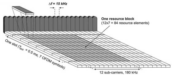
Each user is allocated a number of so-called resource blocks in the time.frequency grid. The more resource blocks a user gets, and the higher the modulation used in the resource elements, the higher the bit-rate. Which resource blocks and how many the user gets at a given point in time depend on advanced scheduling mechanisms in the frequency and time dimensions.
The scheduling mechanisms in LTE are similar to those used in HSPA, and enable optimal performance for different services in different radio environments.
Advantages of OFDM
The primary advantage of OFDM over single-carrier schemes is its ability to cope with severe channel conditions (for example, attenuation of high frequencies in a long copper wire, narrowband interference and frequency-selective fading due to multipath) without complex equalization filters.
Channel equalization is simplified because OFDM may be viewed as using many slowly-modulated narrowband signals rather than one rapidly-modulated wideband signal.
The low symbol rate makes the use of a guard interval between symbols affordable, making it possible to eliminate inter symbol interference (ISI).
This mechanism also facilitates the design of single frequency networks (SFNs), where several adjacent transmitters send the same signal simultaneously at the same frequency, as the signals from multiple distant transmitters may be combined constructively, rather than interfering as would typically occur in a traditional single-carrier system.
Drawbacks of OFDM
High peak-to-average ratio
Sensitive to frequency offset, hence to Doppler-shift as well
SC-FDMA Technology
LTE uses a pre-coded version of OFDM called Single Carrier Frequency Division Multiple Access (SC-FDMA) in the uplink. This is to compensate for a drawback with normal OFDM, which has a very high Peak to Average Power Ratio (PAPR).
High PAPR requires expensive and inefficient power amplifiers with high requirements on linearity, which increases the cost of the terminal and drains the battery faster.
SC-FDMA solves this problem by grouping together the resource blocks in such a way that reduces the need for linearity, and so power consumption, in the power amplifier. A low PAPR also improves coverage and the cell-edge performance.
LTE Glossary
| Term | Description |
|---|---|
| 3GPP | 3rd Generation Partnership Project |
| 3GPP2 | 3rd Generation Partnership Project 2 |
| ARIB | Association of Radio Industries and Businesses |
| ATIS | Alliance for Telecommunication Industry Solutions |
| AWS | Advanced Wireless Services |
| CAPEX | Capital Expenditure |
| CCSA | China Communications Standards Association |
| CDMA | Code Division Multiple Access |
| CDMA2000 | Code Division Multiple Access 2000 |
| DAB | Digital Audio Broadcast |
| DSL | Digital Subscriber Line |
| DVB | Digital Video Broadcast |
| eHSPA | evolved High Speed Packet Access |
| ETSI | European Telecommunications Standards Institute |
| FDD | Frequency Division Duplex |
| FWT | Fixed Wireless Terminal |
| GSM | Global System for Mobile communication |
| HSPA | High Speed Packet Access |
| HSS | Home Subscriber Server |
| IEEE | Institute of Electrical and Electronics Engineers |
| IPTV | Internet Protocol Television |
| LTE | Long Term Evolution |
| MBMS | Multimedia Broadcast Multicast Service |
| MIMO | Multiple Input Multiple Output |
| MME | Mobility Management Entity |
| NGMN | Next Generation Mobile Networks |
| OFDM | Orthogonal Frequency Division Multiplexing |
| OPEX | Operational Expenditure |
| PAPR | Peak to Average Power Ratio |
| PCI | Peripheral Component Interconnect |
| PCRF | Policing and Charging Rules Function |
| PDSN | Packet Data Serving Node |
| PS | Packet Switched |
| QoS | Quality of Service |
| RAN | Radio Access Network |
| SAE | System Architecture Evolution |
| SC-FDMA | Single Carrier Frequency Division Multiple Access |
| SGSN | Serving GPRS Support Node |
| TDD | Time Division Duplex |
| TTA | Telecommunications Technology Association |
| TTC | Telecommunication Technology Committee |
| TTI | Transmission Time Interval |
| UTRA | Universal Terrestrial Radio Access |
| UTRAN | Universal Terrestrial Radio Access Network |
| WCDMA | Wideband Code Division Multiple Access |
| WLAN | Wireless Local Area Network |