- ESP32 for IoT Tutorial
- Home
- Brief Overview of IoT
- Introduction to ESP32
- Installing the ESP32 Board in Arduino IDE
- Setting up RTOS for dual-core and multi-threaded operation
- Interfacing ESP32 with MPU6050
- Interfacing ESP32 with Analog sensors
- ESP32 Preferences
- ESP32 SPIFFS storage (A mini-SD Card in the chip itself)
- Interfacing OLED Display with ESP32
- WiFi on ESP32
- Transmitting data over WiFi using HTTP
- Transmitting data over WiFi using HTTPS
- Transmitting data over WiFi using MQTT
- Transmitting data over Bluetooth
- Getting current time using NTP Client
- Performing the (OTA) update of ESP32 firmware
- Applications of ESP32
- Next steps for you as a developer
- ESP32 for IoT Useful Resources
- Quick Guide
- Useful Resources
- Discussion
Interfacing ESP32 with Analog Sensors
Another important category of sensors that you need to interface with ESP32 is analog sensors. There are many types of analog sensors, LDRs (Light Dependent Resistors), current and voltage sensors being popular examples. Now, if you are familiar with how analogRead works on any Arduino board, like Arduino Uno, then this chapter will be a cakewalk for you because ESP32 uses the same functions. There are only a few nuances you should be aware of, that will be covered in this chapter.
A brief about the Analog to Digital Conversion (ADC) process
Every microcontroller which supports ADC will have a defined resolution and a reference voltage. The reference voltage is generally the supply voltage. The analog voltage provided to the ADC pin should be less than or equal to the reference voltage. The resolution indicates the number of bits that will be used to represent the digital value. Thus, if the resolution is 8 bits, then the value will be represented by 8 bits, and the maximum value possible is 255. This maximum value corresponds to the value of the reference voltage. The values for other voltages are often derived by scaling.
Thus, if the reference voltage is 5V and an 8−bit ADC is used, then 5V corresponds to a reading of 255, 1V corresponds to a reading of (255/5*1) = 51, 2V corresponds to a reading (255/5*2) = 102 and so on. If we had a 12 bit ADC, then 5V would correspond to a reading of 4095, 1V would correspond to a reading of (4095/5*1) = 819, and so on.
The reverse calculations can be performed similarly. If you get a value of 1000 on a 12 bit ADC with a reference voltage of 3.3V, then it corresponds to a value of (1000/4095*3.3) = 0.8V approximately. If you get a reading of 825 on a 10 bit ADC with a reference voltage of 5V, it corresponds to a value of (825/1023*5) = 4.03V approximately.
With the above explanation, it will be clear that both the reference voltage and the number of bits used for ADC determine the minimum possible voltage change that can be detected. If the reference voltage is 5V and the resolution is 12-bit, you have 4095 values to represent a voltage range of 0−5V. Thus, the minimum change that can be detected is 5V/4095 = 1.2mV. Similarly, for a 5V and 8-bit reference voltage, you have only 255 values to represent a range of 0-5V. Thus, the minimum change that can be detected is 5V/255 = 19.6mV, or about 16 times higher than the minimum change detected with a 12-bit resolution.
Connecting the ADC Sensor with ESP32
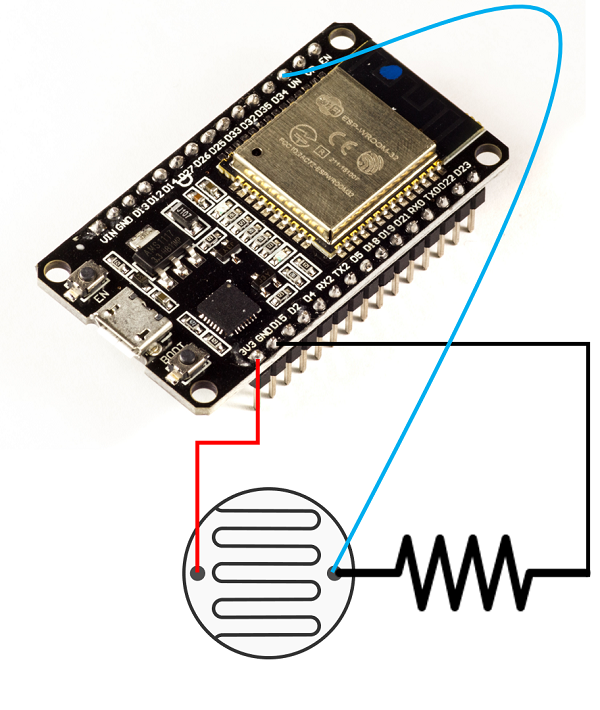
Considering the popularity and availability of the sensor, we will use an LDR for the demonstration. We will essentially connect LDR in series with a regular resistor, and feed the voltage at the point connecting the two resistors to the ADC pin of ESP32. Which pin? Well, there are lots of them. ESP32 boasts of 18 ADC pins (8 in channel 1 and 10 in channel 2). However, channel 2 pins cannot be used along with WiFi. And some pins of channel 1 are not exposed on some boards. Therefore, I generally stick to the following 6 pins for ADC− 32, 33, 34, 35, 36, 39. In the image shown below, an LDR with a resistance of 90K is connected to a resistor of resistance 150K. The free end of the LDR is connected to the 3.3V pin of ESP32 and the free end of the resistor is connected to GND. The common end of the LDR and the resistor is fed to the ADC pin 36 (VN) of ESP32.
Code Walkthrough
GitHub link − https://github.com/
The code here is straightforward. No libraries need to be included. We just define the LDR pin as a constant, initialize serial in the setup(), and set the resolution of the ADC. Here we have set a resolution of 10-bits (meaning the maximum value is 1023). By default the resolution is 12-bits and for ESP32, the minimum possible resolution is 9 bits.
const int LDR_PIN = 36;

void setup() {
   // put your setup code here, to run once:
   Serial.begin(115200);
   analogReadResolution(10); //default is 12. Can be set between 9-12.
}
In the loop, we just read the value from the LDR pin and print it to the serial monitor. Also, we convert it to voltage and print the corresponding voltage as well.
void loop() {
   // put your main code here, to run repeatedly:
   // LDR Resistance: 90k ohms
   // Resistance in series: 150k ohms
   // Pinouts:
   // Vcc −> 3.3 (CONNECTED TO LDR FREE END)
   // Gnd −> Gnd (CONNECTED TO RESISTOR FREE END)
   // Analog Read −> Vp (36) − Intermediate between LDR and resistance.
   int LDR_Reading = analogRead(LDR_PIN);
   float LDR_Voltage = ((float)LDR_Reading*3.3/1023);
   Serial.print("Reading: ");Serial.print(LDR_Reading); Serial.print("\t");Serial.print("Voltage: ");Serial.println(LDR_Voltage);
}
We have used 1023 as the divisor because we have set the ADC resolution to 10 bits. In case you change the ADC value to N, you need to change the divisor to (2^N −1). Now place your hand on the LDR
We have used 1023 as the divisor because we have set the ADC resolution to 10 bits. In case you change the ADC value to N, you need to change the divisor to (2^N −1). Now place your hand on the LDR, and see the effect on the voltage, and then flash a torch on the LDR and see the voltage swing to the opposite extreme on the Serial Monitor. That's it. You've successfully captured data from an analog sensor on ESP32.