- Embedded Systems Basic Tutorial
- ES - Home
- ES - Overview
- ES - Processors
- ES - Architectures
- ES - Tools and Peripherals
- ES - 8051 Microcontroller
- ES - I/O Programming
- ES - Terms
- ES - Assembly Language
- ES - Registers
- ES - Registers Bank/Stack
- ES - Instructions
- ES - Addressing Modes
- ES - Special Function Registers
- ES - Timer/Counter
- ES - Interrupts
- Embedded Systems Resources
- ES - Quick Guide
- ES - Useful Resources
- ES - Discussion
Embedded Systems - Timer/Counter
A timer is a specialized type of clock which is used to measure time intervals. A timer that counts from zero upwards for measuring time elapsed is often called a stopwatch. It is a device that counts down from a specified time interval and used to generate a time delay, for example, an hourglass is a timer.
A counter is a device that stores (and sometimes displays) the number of times a particular event or process occurred, with respect to a clock signal. It is used to count the events happening outside the microcontroller. In electronics, counters can be implemented quite easily using register-type circuits such as a flip-flop.
Difference between a Timer and a Counter
The points that differentiate a timer from a counter are as follows −
| Timer | Counter |
|---|---|
| The register incremented for every machine cycle. | The register is incremented considering 1 to 0 transition at its corresponding to an external input pin (T0, T1). |
| Maximum count rate is 1/12 of the oscillator frequency. | Maximum count rate is 1/24 of the oscillator frequency. |
| A timer uses the frequency of the internal clock, and generates delay. | A counter uses an external signal to count pulses. |
Timers of 8051 and their Associated Registers
The 8051 has two timers, Timer 0 and Timer 1. They can be used as timers or as event counters. Both Timer 0 and Timer 1 are 16-bit wide. Since the 8051 follows an 8-bit architecture, each 16 bit is accessed as two separate registers of low-byte and high-byte.
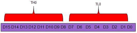
Timer 0 Register
The 16-bit register of Timer 0 is accessed as low- and high-byte. The low-byte register is called TL0 (Timer 0 low byte) and the high-byte register is called TH0 (Timer 0 high byte). These registers can be accessed like any other register. For example, the instruction MOV TL0, #4H moves the value into the low-byte of Timer #0.
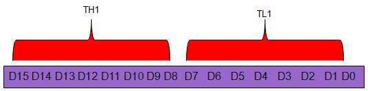
Timer 1 Register
The 16-bit register of Timer 1 is accessed as low- and high-byte. The low-byte register is called TL1 (Timer 1 low byte) and the high-byte register is called TH1 (Timer 1 high byte). These registers can be accessed like any other register. For example, the instruction MOV TL1, #4H moves the value into the low-byte of Timer 1.
TMOD (Timer Mode) Register
Both Timer 0 and Timer 1 use the same register to set the various timer operation modes. It is an 8-bit register in which the lower 4 bits are set aside for Timer 0 and the upper four bits for Timers. In each case, the lower 2 bits are used to set the timer mode in advance and the upper 2 bits are used to specify the location.
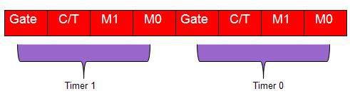
Gate − When set, the timer only runs while INT(0,1) is high.
C/T − Counter/Timer select bit.
M1 − Mode bit 1.
M0 − Mode bit 0.
GATE
Every timer has a means of starting and stopping. Some timers do this by software, some by hardware, and some have both software and hardware controls. 8051 timers have both software and hardware controls. The start and stop of a timer is controlled by software using the instruction SETB TR1 and CLR TR1 for timer 1, and SETB TR0 and CLR TR0 for timer 0.
The SETB instruction is used to start it and it is stopped by the CLR instruction. These instructions start and stop the timers as long as GATE = 0 in the TMOD register. Timers can be started and stopped by an external source by making GATE = 1 in the TMOD register.
C/T (CLOCK / TIMER)
This bit in the TMOD register is used to decide whether a timer is used as a delay generator or an event manager. If C/T = 0, it is used as a timer for timer delay generation. The clock source to create the time delay is the crystal frequency of the 8051. If C/T = 0, the crystal frequency attached to the 8051 also decides the speed at which the 8051 timer ticks at a regular interval.
Timer frequency is always 1/12th of the frequency of the crystal attached to the 8051. Although various 8051 based systems have an XTAL frequency of 10 MHz to 40 MHz, we normally work with the XTAL frequency of 11.0592 MHz. It is because the baud rate for serial communication of the 8051.XTAL = 11.0592 allows the 8051 system to communicate with the PC with no errors.
M1 / M2
| M1 | M2 | Mode |
|---|---|---|
| 0 | 0 | 13-bit timer mode. |
| 0 | 1 | 16-bit timer mode. |
| 1 | 0 | 8-bit auto reload mode. |
| 1 | 1 | Spilt mode. |
Different Modes of Timers
Mode 0 (13-Bit Timer Mode)
Both Timer 1 and Timer 0 in Mode 0 operate as 8-bit counters (with a divide-by-32 prescaler). Timer register is configured as a 13-bit register consisting of all the 8 bits of TH1 and the lower 5 bits of TL1. The upper 3 bits of TL1 are indeterminate and should be ignored. Setting the run flag (TR1) does not clear the register. The timer interrupt flag TF1 is set when the count rolls over from all 1s to all 0s. Mode 0 operation is the same for Timer 0 as it is for Timer 1.
Mode 1 (16-Bit Timer Mode)
Timer mode "1" is a 16-bit timer and is a commonly used mode. It functions in the same way as 13-bit mode except that all 16 bits are used. TLx is incremented starting from 0 to a maximum 255. Once the value 255 is reached, TLx resets to 0 and then THx is incremented by 1. As being a full 16-bit timer, the timer may contain up to 65536 distinct values and it will overflow back to 0 after 65,536 machine cycles.
Mode 2 (8 Bit Auto Reload)
Both the timer registers are configured as 8-bit counters (TL1 and TL0) with automatic reload. Overflow from TL1 (TL0) sets TF1 (TF0) and also reloads TL1 (TL0) with the contents of Th1 (TH0), which is preset by software. The reload leaves TH1 (TH0) unchanged.
The benefit of auto-reload mode is that you can have the timer to always contain a value from 200 to 255. If you use mode 0 or 1, you would have to check in the code to see the overflow and, in that case, reset the timer to 200. In this case, precious instructions check the value and/or get reloaded. In mode 2, the microcontroller takes care of this. Once you have configured a timer in mode 2, you don't have to worry about checking to see if the timer has overflowed, nor do you have to worry about resetting the value because the microcontroller hardware will do it all for you. The auto-reload mode is used for establishing a common baud rate.
Mode 3 (Split Timer Mode)
Timer mode "3" is known as split-timer mode. When Timer 0 is placed in mode 3, it becomes two separate 8-bit timers. Timer 0 is TL0 and Timer 1 is TH0. Both the timers count from 0 to 255 and in case of overflow, reset back to 0. All the bits that are of Timer 1 will now be tied to TH0.
When Timer 0 is in split mode, the real Timer 1 (i.e. TH1 and TL1) can be set in modes 0, 1 or 2, but it cannot be started/stopped as the bits that do that are now linked to TH0. The real timer 1 will be incremented with every machine cycle.
Initializing a Timer
Decide the timer mode. Consider a 16-bit timer that runs continuously, and is independent of any external pins.
Initialize the TMOD SFR. Use the lowest 4 bits of TMOD and consider Timer 0. Keep the two bits, GATE 0 and C/T 0, as 0, since we want the timer to be independent of the external pins. As 16-bit mode is timer mode 1, clear T0M1 and set T0M0. Effectively, the only bit to turn on is bit 0 of TMOD. Now execute the following instruction −
MOV TMOD,#01h
Now, Timer 0 is in 16-bit timer mode, but the timer is not running. To start the timer in running mode, set the TR0 bit by executing the following instruction −
SETB TR0
Now, Timer 0 will immediately start counting, being incremented once every machine cycle.
Reading a Timer
A 16-bit timer can be read in two ways. Either read the actual value of the timer as a 16-bit number, or you detect when the timer has overflowed.
Detecting Timer Overflow
When a timer overflows from its highest value to 0, the microcontroller automatically sets the TFx bit in the TCON register. So instead of checking the exact value of the timer, the TFx bit can be checked. If TF0 is set, then Timer 0 has overflowed; if TF1 is set, then Timer 1 has overflowed.