- Embedded Systems Basic Tutorial
- ES - Home
- ES - Overview
- ES - Processors
- ES - Architectures
- ES - Tools and Peripherals
- ES - 8051 Microcontroller
- ES - I/O Programming
- ES - Terms
- ES - Assembly Language
- ES - Registers
- ES - Registers Bank/Stack
- ES - Instructions
- ES - Addressing Modes
- ES - Special Function Registers
- ES - Timer/Counter
- ES - Interrupts
- Embedded Systems Resources
- ES - Quick Guide
- ES - Useful Resources
- ES - Discussion
Embedded Systems - Addressing Modes
An addressing mode refers to how you are addressing a given memory location. There are five different ways or five addressing modes to execute this instruction which are as follows −
- Immediate addressing mode
- Direct addressing mode
- Register direct addressing mode
- Register indirect addressing mode
- Indexed addressing mode
Immediate Addressing Mode
Let's begin with an example.
MOV A, #6AH
In general, we can write,
MOV A, #data
It is termed as immediate because 8-bit data is transferred immediately to the accumulator (destination operand).
The following illustration describes the above instruction and its execution. The opcode 74H is saved at 0202 address. The data 6AH is saved at 0203 address in the program memory. After reading the opcode 74H, the data at the next program memory address is transferred to accumulator A (E0H is the address of accumulator). Since the instruction is of 2-bytes and is executed in one cycle, the program counter will be incremented by 2 and will point to 0204 of the program memory.
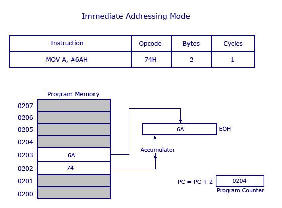
Note − The '#' symbol before 6AH indicates that the operand is a data (8 bit). In the absence of '#', the hexadecimal number would be taken as an address.
Direct Addressing Mode
This is another way of addressing an operand. Here, the address of the data (source data) is given as an operand. Let’s take an example.
MOV A, 04H
The register bank#0 (4th register) has the address 04H. When the MOV instruction is executed, the data stored in register 04H is moved to the accumulator. As the register 04H holds the data 1FH, 1FH is moved to the accumulator.
Note − We have not used '#' in direct addressing mode, unlike immediate mode. If we had used '#', the data value 04H would have been transferred to the accumulator instead of 1FH.
Now, take a look at the following illustration. It shows how the instruction gets executed.
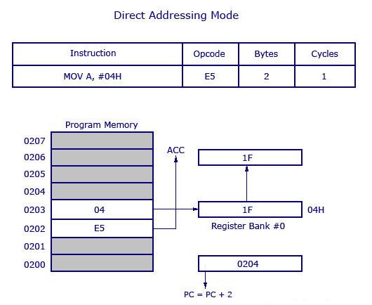
As shown in the above illustration, this is a 2-byte instruction which requires 1 cycle to complete. The PC will be incremented by 2 and will point to 0204. The opcode for the instruction MOV A, address is E5H. When the instruction at 0202 is executed (E5H), the accumulator is made active and ready to receive data. Then the PC goes to the next address as 0203 and looks up the address of the location of 04H where the source data (to be transferred to accumulator) is located. At 04H, the control finds the data 1F and transfers it to the accumulator and hence the execution is completed.
Register Direct Addressing Mode
In this addressing mode, we use the register name directly (as source operand). Let us try to understand with the help of an example.
MOV A, R4
At a time, the registers can take values from R0 to R7. There are 32 such registers. In order to use 32 registers with just 8 variables to address registers, register banks are used. There are 4 register banks named from 0 to 3. Each bank comprises of 8 registers named from R0 to R7.
At a time, a single register bank can be selected. Selection of a register bank is made possible through a Special Function Register (SFR) named Processor Status Word (PSW). PSW is an 8-bit SFR where each bit can be programmed as required. Bits are designated from PSW.0 to PSW.7. PSW.3 and PSW.4 are used to select register banks.
Now, take a look at the following illustration to get a clear understanding of how it works.
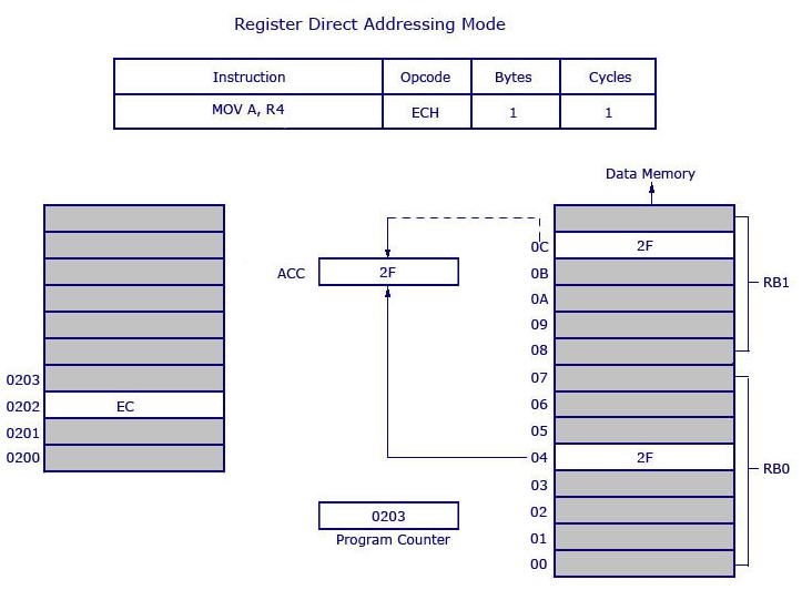
Opcode EC is used for MOV A, R4. The opcode is stored at the address 0202 and when it is executed, the control goes directly to R4 of the respected register bank (that is selected in PSW). If register bank #0 is selected, then the data from R4 of register bank #0 will be moved to the accumulator. Here 2F is stored at 04H. 04H represents the address of R4 of register bank #0.
Data (2F) movement is highlighted in bold. 2F is getting transferred to the accumulator from data memory location 0C H and is shown as dotted line. 0CH is the address location of Register 4 (R4) of register bank #1. The instruction above is 1 byte and requires 1 cycle for complete execution. What it means is, you can save program memory by using register direct addressing mode.
Register Indirect Addressing Mode
In this addressing mode, the address of the data is stored in the register as operand.
MOV A, @R0
Here the value inside R0 is considered as an address, which holds the data to be transferred to the accumulator. Example: If R0 has the value 20H, and data 2FH is stored at the address 20H, then the value 2FH will get transferred to the accumulator after executing this instruction. See the following illustration.
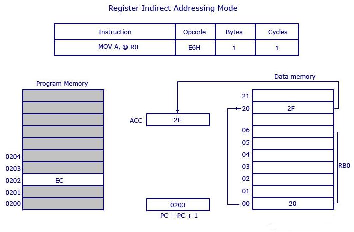
So the opcode for MOV A, @R0 is E6H. Assuming that the register bank #0 is selected, the R0 of register bank #0 holds the data 20H. Program control moves to 20H where it locates the data 2FH and it transfers 2FH to the accumulator. This is a 1-byte instruction and the program counter increments by 1 and moves to 0203 of the program memory.
Note − Only R0 and R1 are allowed to form a register indirect addressing instruction. In other words, the programmer can create an instruction either using @R0 or @R1. All register banks are allowed.
Indexed Addressing Mode
We will take two examples to understand the concept of indexed addressing mode. Take a look at the following instructions −
MOVC A, @A+DPTR
and
MOVC A, @A+PC
where DPTR is the data pointer and PC is the program counter (both are 16-bit registers). Consider the first example.
MOVC A, @A+DPTR
The source operand is @A+DPTR. It contains the source data from this location. Here we are adding the contents of DPTR with the current content of the accumulator. This addition will give a new address which is the address of the source data. The data pointed by this address is then transferred to the accumulator.
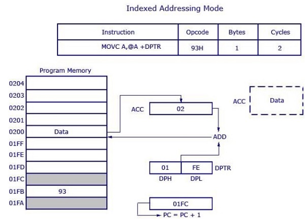
The opcode is 93H. DPTR has the value 01FE, where 01 is located in DPH (higher 8 bits) and FE is located in DPL (lower 8 bits). Accumulator has the value 02H. Then a 16-bit addition is performed and 01FE H+02H results in 0200 H. Data at the location 0200H will get transferred to the accumulator. The previous value inside the accumulator (02H) will be replaced with the new data from 0200H. The new data in the accumulator is highlighted in the illustration.
This is a 1-byte instruction with 2 cycles needed for execution and the execution time required for this instruction is high compared to previous instructions (which were all 1 cycle each).
The other example MOVC A, @A+PC works the same way as the above example. Instead of adding DPTR with the accumulator, here the data inside the program counter (PC) is added with the accumulator to obtain the target address.