- Electronic Circuits Tutorial
- Electronic Circuits - Home
- Electronic Circuits - Introduction
- Electronic Circuits - Signals
- Wave Shaping
- Linear Wave Shapping
- Special Functions of LPF and HPF
- Nonlinear Wave Shapping
- Positive Clipper Circuits
- Negative Clipper Circuits
- Clamper Circuits
- Limiter & Voltage Multiplier
- Diode as a Switch
- Power Supplies
- Power Supplies
- Electronic Circuits - Rectifiers
- Full Wave Rectifiers
- Electronic Circuits - Filters
- Electronic Circuits - Regulators
- Electronic Circuits - SMPS
- Electronic Circuits Resources
- Electronic Circuits - Quick Guide
- Electronic Circuits - Resources
- Electronic Circuits - Discussion
Electronic Circuits - Clamper Circuits
A Clamper Circuit is a circuit that adds a DC level to an AC signal. Actually, the positive and negative peaks of the signals can be placed at desired levels using the clamping circuits. As the DC level gets shifted, a clamper circuit is called as a Level Shifter.
Clamper circuits consist of energy storage elements like capacitors. A simple clamper circuit comprises of a capacitor, a diode, a resistor and a dc battery if required.
Clamper Circuit
A Clamper circuit can be defined as the circuit that consists of a diode, a resistor and a capacitor that shifts the waveform to a desired DC level without changing the actual appearance of the applied signal.
In order to maintain the time period of the wave form, the tau must be greater than, half the time period (discharging time of the capacitor should be slow.)
$$\tau = Rc$$
Where
- R is the resistance of the resistor employed
- C is the capacitance of the capacitor used
The time constant of charge and discharge of the capacitor determines the output of a clamper circuit.
In a clamper circuit, a vertical shift of upward or downward takes place in the output waveform with respect to the input signal.
The load resistor and the capacitor affect the waveform. So, the discharging time of the capacitor should be large enough.
The DC component present in the input is rejected when a capacitor coupled network is used (as a capacitor blocks dc). Hence when dc needs to be restored, clamping circuit is used.
Types of Clampers
There are few types of clamper circuits, such as
- Positive Clamper
- Positive clamper with positive $V_r$
- Positive clamper with negative $V_r$
- Negative Clamper
- Negative clamper with positive $V_{r}$
- Negative clamper with negative $V_{r}$
Let us go through them in detail.
Positive Clamper Circuit
A Clamping circuit restores the DC level. When a negative peak of the signal is raised above to the zero level, then the signal is said to be positively clamped.
A Positive Clamper circuit is one that consists of a diode, a resistor and a capacitor and that shifts the output signal to the positive portion of the input signal. The figure below explains the construction of a positive clamper circuit.
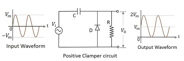
Initially when the input is given, the capacitor is not yet charged and the diode is reverse biased. The output is not considered at this point of time. During the negative half cycle, at the peak value, the capacitor gets charged with negative on one plate and positive on the other. The capacitor is now charged to its peak value $V_{m}$. The diode is forward biased and conducts heavily.
During the next positive half cycle, the capacitor is charged to positive Vm while the diode gets reverse biased and gets open circuited. The output of the circuit at this moment will be
$$V_{0}=V_{i}+V_{m}$$
Hence the signal is positively clamped as shown in the above figure. The output signal changes according to the changes in the input, but shifts the level according to the charge on the capacitor, as it adds the input voltage.
Positive Clamper with Positive Vr
A Positive clamper circuit if biased with some positive reference voltage, that voltage will be added to the output to raise the clamped level. Using this, the circuit of the positive clamper with positive reference voltage is constructed as below.
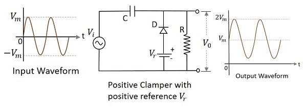
During the positive half cycle, the reference voltage is applied through the diode at the output and as the input voltage increases, the cathode voltage of the diode increase with respect to the anode voltage and hence it stops conducting. During the negative half cycle, the diode gets forward biased and starts conducting. The voltage across the capacitor and the reference voltage together maintain the output voltage level.
Positive Clamper with Negative $V_{r}$
A Positive clamper circuit if biased with some negative reference voltage, that voltage will be added to the output to raise the clamped level. Using this, the circuit of the positive clamper with positive reference voltage is constructed as below.
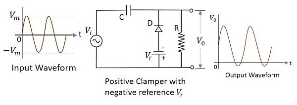
During the positive half cycle, the voltage across the capacitor and the reference voltage together maintain the output voltage level. During the negative half-cycle, the diode conducts when the cathode voltage gets less than the anode voltage. These changes make the output voltage as shown in the above figure.
Negative Clamper
A Negative Clamper circuit is one that consists of a diode, a resistor and a capacitor and that shifts the output signal to the negative portion of the input signal. The figure below explains the construction of a negative clamper circuit.
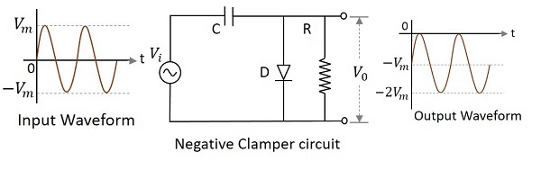
During the positive half cycle, the capacitor gets charged to its peak value $v_{m}$. The diode is forward biased and conducts. During the negative half cycle, the diode gets reverse biased and gets open circuited. The output of the circuit at this moment will be
$$V_{0}=V_{i}+V_{m}$$
Hence the signal is negatively clamped as shown in the above figure. The output signal changes according to the changes in the input, but shifts the level according to the charge on the capacitor, as it adds the input voltage.
Negative clamper with positive Vr
A Negative clamper circuit if biased with some positive reference voltage, that voltage will be added to the output to raise the clamped level. Using this, the circuit of the negative clamper with positive reference voltage is constructed as below.
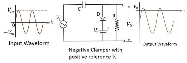
Though the output voltage is negatively clamped, a portion of the output waveform is raised to the positive level, as the applied reference voltage is positive. During the positive half-cycle, the diode conducts, but the output equals the positive reference voltage applied. During the negative half cycle, the diode acts as open circuited and the voltage across the capacitor forms the output.
Negative Clamper with Negative Vr
A Negative clamper circuit if biased with some negative reference voltage, that voltage will be added to the output to raise the clamped level. Using this, the circuit of the negative clamper with negative reference voltage is constructed as below.
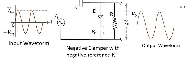
The cathode of the diode is connected with a negative reference voltage, which is less than that of zero and the anode voltage. Hence the diode starts conducting during positive half cycle, before the zero voltage level. During the negative half cycle, the voltage across the capacitor appears at the output. Thus the waveform is clamped towards the negative portion.
Applications
There are many applications for both Clippers and Clampers such as
Clippers
- Used for the generation and shaping of waveforms
- Used for the protection of circuits from spikes
- Used for amplitude restorers
- Used as voltage limiters
- Used in television circuits
- Used in FM transmitters
Clampers
- Used as direct current restorers
- Used to remove distortions
- Used as voltage multipliers
- Used for the protection of amplifiers
- Used as test equipment
- Used as base-line stabilizer