- Electronic Circuits Tutorial
- Electronic Circuits - Home
- Electronic Circuits - Introduction
- Electronic Circuits - Signals
- Wave Shaping
- Linear Wave Shapping
- Special Functions of LPF and HPF
- Nonlinear Wave Shapping
- Positive Clipper Circuits
- Negative Clipper Circuits
- Clamper Circuits
- Limiter & Voltage Multiplier
- Diode as a Switch
- Power Supplies
- Power Supplies
- Electronic Circuits - Rectifiers
- Full Wave Rectifiers
- Electronic Circuits - Filters
- Electronic Circuits - Regulators
- Electronic Circuits - SMPS
- Electronic Circuits Resources
- Electronic Circuits - Quick Guide
- Electronic Circuits - Resources
- Electronic Circuits - Discussion
Special Functions of LPF and HPF
Low-pass and high-pass filter circuits are used as special circuits in many applications. Low-pass filter (LPF) can work as an Integrator, whereas the high-pass filter (HPF) can work as a Differentiator. These two mathematical functions are possible only with these circuits which reduce the efforts of an electronics engineer in many applications.
Low Pass Filter as Integrator
At low frequencies, the capacitive reactance tends to become infinite and at high frequencies the reactance becomes zero. Hence at low frequencies, the LPF has finite output and at high frequencies the output is nil, which is same for an integrator circuit. Hence low pass filter can be said to be worked as an integrator.
For the LPF to behave as an integrator
$$\tau \gg T$$
Where $\tau = RC$ the time constant of the circuit
Then the voltage variation in C is very small.
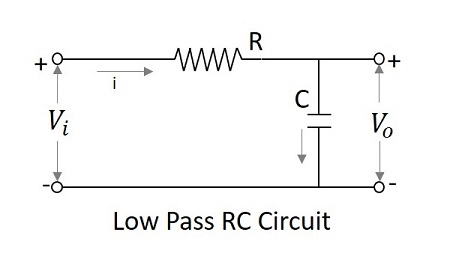
$$V_{i}=iR+\frac{1}{C} \int i \:dt$$
$$V_{i}\cong iR$$
$$Since \:\: \frac{1}{C} \int i \:dt \ll iR$$
$$i=\frac{V_{i}}{R}$$
$$ Since \:\: V_{0}=\frac{1}{C}\int i dt =\frac{1}{RC}\int V_{i}dt=\frac{1}{\tau }\int V_{i} dt$$
$$Output \propto \int input$$
Hence a LPF with large time constant produces an output that is proportional to the integral of an input.
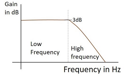
Frequency Response
The Frequency response of a practical low pass filter, when it works as an Integrator is as shown below.
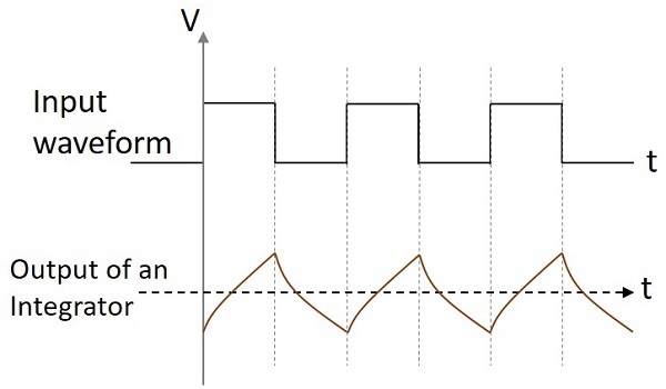
Output Waveform
If the integrator circuit is given a sinewave input, the output will be a cosine wave. If the input is a square wave, the output wave form changes its shape and appears as in the figure below.
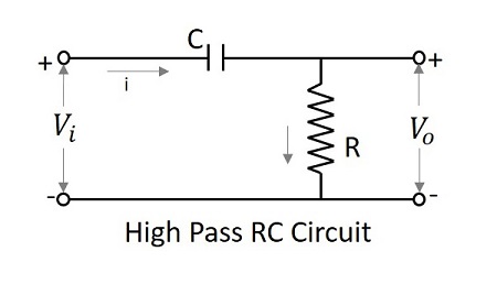
High Pass Filter as Differentiator
At low frequencies, the output of a differentiator is zero whereas at high frequencies, its output is of some finite value. This is same as for a differentiator. Hence the high pass filter is said to be behaved as a differentiator.
If time constant of the RC HPF is very much smaller than time period of the input signal, then circuit behaves as a differentiator. Then the voltage drop across R is very small when compared to the drop across C.
$$V_{i}=\frac{1}{C}\int i \:dt +iR$$
But $iR=V_{0}$ is small
$$since V_{i}=\frac{1}{C}\int i \:dt$$
$$i=\frac{V_{0}}{R}$$
$$Since \: V_{i} =\frac{1}{\tau }\int V_{0} \:dt$$
Where $\tau =RC$ the time constant of the circuit.
Differentiating on both sides,
$$\frac{dV_{i}}{dt}=\frac{V_0}{\tau }$$
$$V_{0}=\tau \frac{dV_{i}}{dt}$$
$$Since \:V_{0}\propto \frac{dV_{i}}{dt}$$
The output is proportional to the differential of the input signal.
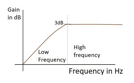
Frequency Response
The Frequency response of a practical high pass filter, when it works as a Differentiator is as shown below.
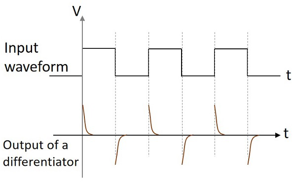
Output Wave form
If the differentiator circuit is given a sinewave input, the output will be a cosine wave. If the input is a square wave, the output wave form changes its shape and appears as in the figure below.
These two circuits are mostly used in various electronic applications. A differentiator circuit produces a constant output voltage when the input applied tends to change steadily. An integrator circuit produces a steadily changing output voltage when the input voltage applied is constant.