- Electronic Circuits Tutorial
- Electronic Circuits - Home
- Electronic Circuits - Introduction
- Electronic Circuits - Signals
- Wave Shaping
- Linear Wave Shapping
- Special Functions of LPF and HPF
- Nonlinear Wave Shapping
- Positive Clipper Circuits
- Negative Clipper Circuits
- Clamper Circuits
- Limiter & Voltage Multiplier
- Diode as a Switch
- Power Supplies
- Power Supplies
- Electronic Circuits - Rectifiers
- Full Wave Rectifiers
- Electronic Circuits - Filters
- Electronic Circuits - Regulators
- Electronic Circuits - SMPS
- Electronic Circuits Resources
- Electronic Circuits - Quick Guide
- Electronic Circuits - Resources
- Electronic Circuits - Discussion
Electronic Circuits - Signals
A Signal can be understood as "a representation that gives some information about the data present at the source from which it is produced." This is usually time varying. Hence, a signal can be a source of energy which transmits some information. This can easily be represented on a graph.
Examples
- An alarm gives a signal that it’s time.
- A cooker whistle confirms that the food is cooked.
- A red light signals some danger.
- A traffic signal indicates your move.
- A phone rings signaling a call for you.
A signal can be of any type that conveys some information. This signal produced from an electronic equipment, is called as Electronic Signal or Electrical Signal. These are generally time variants.
Types of Signals
Signals can be classified either as Analog or Digital, depending upon their characteristics. Analog and Digital signals can be further classified, as shown in the following image.
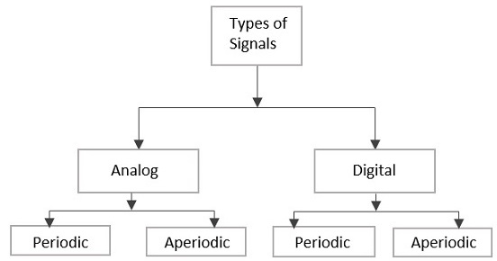
Analog Signal
A continuous time-varying signal, which represents a time-varying quantity, can be termed as an Analog Signal. This signal keeps on varying with respect to time, according to the instantaneous values of the quantity, which represents it.
Digital Signal
A signal which is discrete in nature or which is non-continuous in form can be termed as a Digital signal. This signal has individual values, denoted separately, which are not based on previous values, as if they are derived at that particular instant of time.
Periodic Signal & Aperiodic Signal
Any analog or digital signal, that repeats its pattern over a period of time, is called as a Periodic Signal. This signal has its pattern continued repeatedly and is easy to be assumed or to be calculated.
Any analog or digital signal, that doesn’t repeat its pattern over a period of time, is called as Aperiodic Signal. This signal has its pattern continued but the pattern is not repeated and is not so easy to be assumed or to be calculated.
Signals & Notations
Among the Periodic Signals, the most commonly used signals are Sine wave, Cosine wave, Triangular waveform, Square wave, Rectangular wave, Saw-tooth waveform, Pulse waveform or pulse train etc. let us have a look at those waveforms.
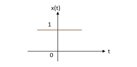
Unit Step Signal
The unit step signal has the value of one unit from its origin to one unit on the X-axis. This is mostly used as a test signal. The image of unit step signal is shown below.
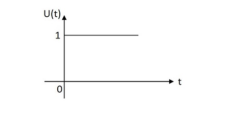
The unit step function is denoted by $u\left ( t \right )$. It is defined as −
$$u\left ( t \right )=\left\{\begin{matrix}1 & t\geq 0\\ 0 & t< 0\end{matrix}\right.$$
Unit Impulse Signal
The unit impulse signal has the value of one unit at its origin. Its area is one unit. The image of unit impulse signal is shown below.
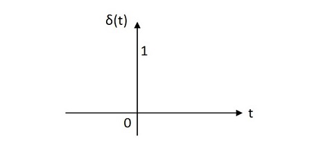
The unit impulse function is denoted by ẟ(t). It is defined as
$$\delta \left ( t \right )=\left\{\begin{matrix} \infty \:\:if \:\:t=0\\0 \:\:if \:\:t\neq 0\end{matrix}\right.$$
$$\int_{-\infty }^{\infty }\delta \left ( t \right )d\left ( t \right )=1$$
$$\int_{-\infty }^{t }\delta \left ( t \right )d\left ( t \right )=u\left ( t \right )$$
$$\delta \left ( t \right )=\frac{du\left ( t \right )}{d\left ( t \right )} $$
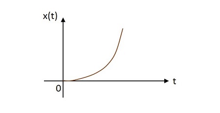
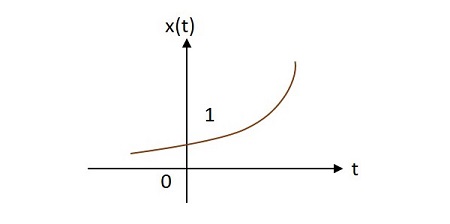
Unit Ramp Signal
The unit ramp signal has its value increasing exponentially from its origin. The image of unit ramp signal is shown below.
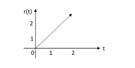
The unit ramp function is denoted by u(t). It is defined as −
$$\int_{0}^{t}u\left ( t \right ) d\left ( t \right )=\int_{0}^{t} 1 dt =t=r\left ( t \right )$$
$$u\left ( t \right )=\frac{dr\left ( t \right )}{dt}$$
Unit Parabolic Signal
The unit parabolic signal has its value altering like a parabola at its origin. The image of unit parabolic signal is shown below.
The unit parabolic function is denoted by $u\left ( t \right )$. It is defined as −
$$\int_{0}^{t}\int_{0}^{t}u\left ( t \right )dtdt=\int_{0}^{t}r\left ( t \right )dt=\int_{0}^{t} t.dt=\frac{t^{2}}{2}dt=x\left ( t \right )$$
$$r\left ( t \right )=\frac{dx\left ( t \right )}{dt}$$
$$u\left ( t \right )=\frac{d^{2}x\left ( t \right )}{dt^{2}}$$
Signum Function
The Signum function has its value equally distributed in both positive and negative planes from its origin. The image of Signum function is shown below.
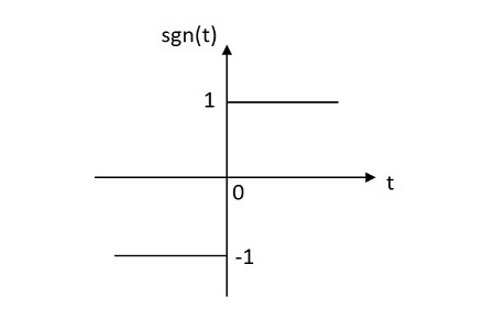
The Signum function is denoted by sgn(t). It is defined as
$$sgn\left ( t \right )=\left\{\begin{matrix} 1 \:\: for \:\: t\geq 0\\-1 \:\: for \:\:t < 0\end{matrix}\right.$$
$$sgn\left ( t \right )=2u\left ( t \right ) -1$$
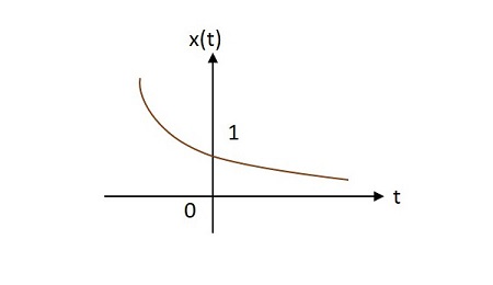
Exponential Signal
The exponential signal has its value varying exponentially from its origin. The exponential function is in the form of −
$$x\left ( t \right ) =e^{\alpha t}$$
The shape of exponential can be defined by $\alpha$. This function can be understood in 3 cases
Case 1 −
If $\alpha = 0\rightarrow x\left ( t \right )=e^{0}=1$
Case 2 −
If $\alpha <0$ then $x\left ( t \right )=e^{\alpha t}$ where $\alpha$ is negative. This shape is called as decaying exponential.
Case 3 −
If $\alpha > 0$ then $x\left ( t \right )=e^{\alpha t}$ where $\alpha$ is positive. This shape is called as raising exponential.
Rectangular Signal
The rectangular signal has its value distributed in rectangular shape in both positive and negative planes from its origin. The image of rectangular signal is shown below.
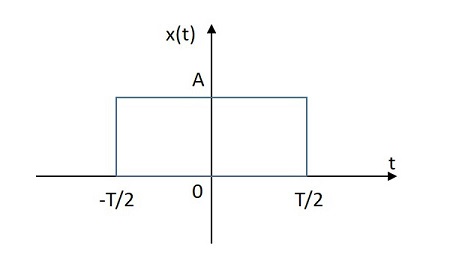
The rectangular function is denoted by $x\left ( t \right )$. It is defined as
$$x\left ( t \right )=A \:rect\left [ \frac{t}{T} \right ]$$
Triangular Signal
The rectangular signal has its value distributed in triangular shape in both positive and negative planes from its origin. The image of triangular signal is shown below.
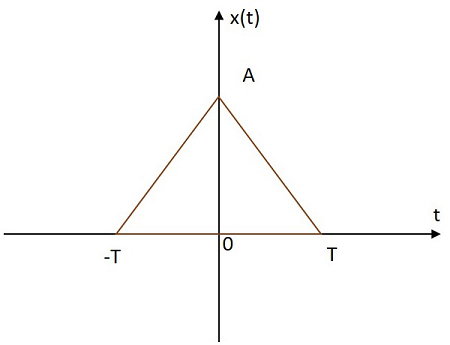
The triangular function is denoted by$x\left ( t \right )$. It is defined as
$$x\left ( t \right )=A \left [ 1-\frac{\left | t \right |}{T} \right ]$$
Sinusoidal Signal
The Sinusoidal signal has its value varying sinusoidally from its origin. The image of Sinusoidal signal is shown below.
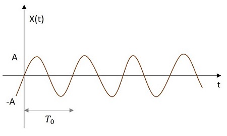
The sinusoidal function is denoted by x (t). It is defined as −
$$x\left ( t \right )=A \cos \left ( w_{0} t\pm \phi \right )$$
or
$$x\left ( t \right )=A sin\left ( w_{0}t\pm \phi \right )$$
Where $T_{0}=\frac{2 \pi}{w_{0}}$
Sinc Function
The Sinc signal has its value varying according to a particular relation as in given equation below. It has its maximum value at the origin and goes on decreasing as it moves away. The image of a Sinc function signal is shown below.
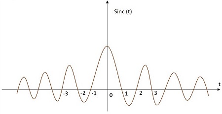
The Sinc function is denoted by sinc(t). It is defined as −
$$sinc\left ( t \right )=\frac{sin\left ( \pi t \right )}{\pi t}$$
So, these are the different signals we mostly come across in the field of Electronics and Communications. Every signal can be defined in a mathematical equation to make the signal analysis easier.
Each signal has a particular wave shape as mentioned before. The shaping of the wave may alter the content present in the signal. Anyways, it is the decision to be made by the design engineer whether to alter a wave or not for any particular circuit. But, to alter the shape of the wave, there are few techniques which will be discussed in further units