- Electronic Circuits Tutorial
- Electronic Circuits - Home
- Electronic Circuits - Introduction
- Electronic Circuits - Signals
- Wave Shaping
- Linear Wave Shapping
- Special Functions of LPF and HPF
- Nonlinear Wave Shapping
- Positive Clipper Circuits
- Negative Clipper Circuits
- Clamper Circuits
- Limiter & Voltage Multiplier
- Diode as a Switch
- Power Supplies
- Power Supplies
- Electronic Circuits - Rectifiers
- Full Wave Rectifiers
- Electronic Circuits - Filters
- Electronic Circuits - Regulators
- Electronic Circuits - SMPS
- Electronic Circuits Resources
- Electronic Circuits - Quick Guide
- Electronic Circuits - Resources
- Electronic Circuits - Discussion
Electronic Circuits - Filters
The power supply block diagram clearly explains that a filter circuit is needed after the rectifier circuit. A rectifier helps in converting a pulsating alternating current to direct current, which flows only in one direction. Till now, we have seen different types of rectifier circuits.
The outputs of all these rectifier circuits contains some ripple factor. We have also observed that the ripple factor of a half wave rectifier is greater than that of a full wave rectifier.
Why Do We Need Filters?
The ripple in the signal denotes the presence of some AC component. This ac component has to be completely removed in order to get pure dc output. So, we need a circuit that smoothens the rectified output into a pure dc signal.
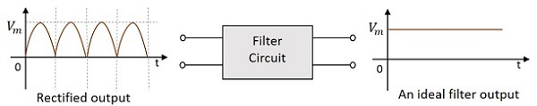
A filter circuit is one which removes the ac component present in the rectified output and allows the dc component to reach the load.
The following figure shows the functionality of a filter circuit.
A filter circuit is constructed using two main components, inductor and capacitor. We have already studied in Basic Electronics tutorial that
An inductor allows dc and blocks ac.
A capacitor allows ac and blocks dc.
Let us try to construct a few filters, using these two components.
Series Inductor Filter
As an inductor allows dc and blocks ac, a filter called Series Inductor Filter can be constructed by connecting the inductor in series, between the rectifier and the load. The figure below shows the circuit of a series inductor filter.
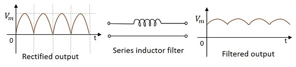
The rectified output when passed through this filter, the inductor blocks the ac components that are present in the signal, in order to provide a pure dc. This is a simple primary filter.
Shunt Capacitor Filter
As a capacitor allows ac through it and blocks dc, a filter called Shunt Capacitor Filter can be constructed using a capacitor, connected in shunt, as shown in the following figure.
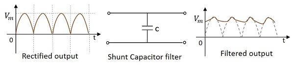
The rectified output when passed through this filter, the ac components present in the signal are grounded through the capacitor which allows ac components. The remaining dc components present in the signal are collected at the output.
The above filter types discussed are constructed using an inductor or a capacitor. Now, let’s try to use both of them to make a better filter. These are combinational filters.
L-C Filter
A filter circuit can be constructed using both inductor and capacitor in order to obtain a better output where the efficiencies of both inductor and capacitor can be used. The figure below shows the circuit diagram of a LC filter.
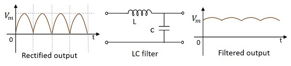
The rectified output when given to this circuit, the inductor allows dc components to pass through it, blocking the ac components in the signal. Now, from that signal, few more ac components if any present are grounded so that we get a pure dc output.
This filter is also called as a Choke Input Filter as the input signal first enters the inductor. The output of this filter is a better one than the previous ones.
Π- Filter (Pi filter)
This is another type of filter circuit which is very commonly used. It has capacitor at its input and hence it is also called as a Capacitor Input Filter. Here, two capacitors and one inductor are connected in the form of π shaped network. A capacitor in parallel, then an inductor in series, followed by another capacitor in parallel makes this circuit.
If needed, several identical sections can also be added to this, according to the requirement. The figure below shows a circuit for $\pi$ filter (Pi-filter).
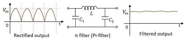
Working of a Pi filter
In this circuit, we have a capacitor in parallel, then an inductor in series, followed by another capacitor in parallel.
Capacitor C1 − This filter capacitor offers high reactance to dc and low reactance to ac signal. After grounding the ac components present in the signal, the signal passes to the inductor for further filtration.
Inductor L − This inductor offers low reactance to dc components, while blocking the ac components if any got managed to pass, through the capacitor C1.
Capacitor C2 − Now the signal is further smoothened using this capacitor so that it allows any ac component present in the signal, which the inductor has failed to block.
Thus we, get the desired pure dc output at the load.