- Digital Communication Tutorial
- Digital Communication - Home
- Analog to Digital
- Pulse Code Modulation
- Sampling
- Quantization
- Differential PCM
- Delta Modulation
- Techniques
- Line Codes
- Data Encoding Techniques
- Pulse Shaping
- Digital Modulation Techniques
- Amplitude Shift Keying
- Frequency Shift Keying
- Phase Shift Keying
- Quadrature Phase Shift Keying
- Differential Phase Shift Keying
- M-ary Encoding
- Information Theory
- Source Coding Theorem
- Channel Coding Theorem
- Error Control Coding
- Spread Spectrum Modulation
- Digital Communication Resources
- Quick Guide
- Digital Communication - Resources
- Digital Communication - Discussion
Frequency Shift Keying
Frequency Shift Keying (FSK) is the digital modulation technique in which the frequency of the carrier signal varies according to the digital signal changes. FSK is a scheme of frequency modulation.
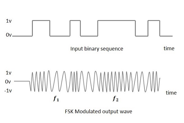
The output of a FSK modulated wave is high in frequency for a binary High input and is low in frequency for a binary Low input. The binary 1s and 0s are called Mark and Space frequencies.
The following image is the diagrammatic representation of FSK modulated waveform along with its input.
To find the process of obtaining this FSK modulated wave, let us know about the working of a FSK modulator.
FSK Modulator
The FSK modulator block diagram comprises of two oscillators with a clock and the input binary sequence. Following is its block diagram.
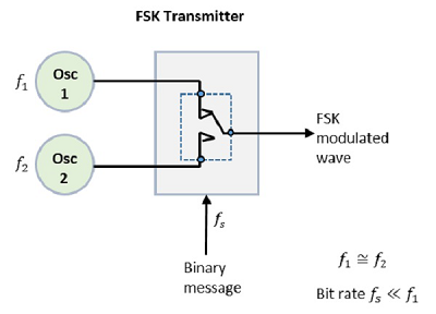
The two oscillators, producing a higher and a lower frequency signals, are connected to a switch along with an internal clock. To avoid the abrupt phase discontinuities of the output waveform during the transmission of the message, a clock is applied to both the oscillators, internally. The binary input sequence is applied to the transmitter so as to choose the frequencies according to the binary input.
FSK Demodulator
There are different methods for demodulating a FSK wave. The main methods of FSK detection are asynchronous detector and synchronous detector. The synchronous detector is a coherent one, while asynchronous detector is a non-coherent one.
Asynchronous FSK Detector
The block diagram of Asynchronous FSK detector consists of two band pass filters, two envelope detectors, and a decision circuit. Following is the diagrammatic representation.
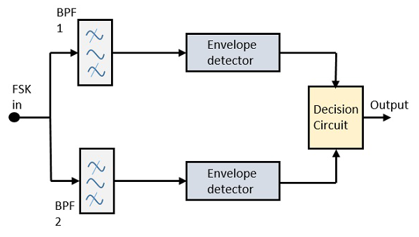
The FSK signal is passed through the two Band Pass Filters (BPFs), tuned to Space and Mark frequencies. The output from these two BPFs look like ASK signal, which is given to the envelope detector. The signal in each envelope detector is modulated asynchronously.
The decision circuit chooses which output is more likely and selects it from any one of the envelope detectors. It also re-shapes the waveform to a rectangular one.
Synchronous FSK Detector
The block diagram of Synchronous FSK detector consists of two mixers with local oscillator circuits, two band pass filters and a decision circuit. Following is the diagrammatic representation.
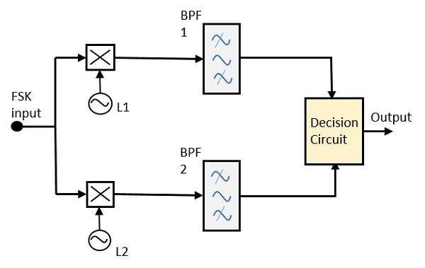
The FSK signal input is given to the two mixers with local oscillator circuits. These two are connected to two band pass filters. These combinations act as demodulators and the decision circuit chooses which output is more likely and selects it from any one of the detectors. The two signals have a minimum frequency separation.
For both of the demodulators, the bandwidth of each of them depends on their bit rate. This synchronous demodulator is a bit complex than asynchronous type demodulators.