- Analog Communication Tutorial
- Analog Communication - Home
- Introduction
- Modulation
- Amplitude Modulation
- Numerical Problems 1
- AM Modulators
- AM Demodulators
- DSBSC Modulation
- DSBSC Modulators
- DSBSC Demodulators
- SSBSC Modulation
- SSBSC Modulators
- SSBSC Demodulator
- VSBSC Modulation
- Angle Modulation
- Numerical Problems 2
- FM Modulators
- FM Demodulators
- Multiplexing
- Noise
- SNR Calculations
- Transmitters
- Receivers
- Sampling
- Pulse Modulation
- Transducers
- Analog Communication Resources
- Quick Guide
- Analog Communication - Resources
- Analog Communication - Discussion
DSBSC Demodulators
The process of extracting an original message signal from DSBSC wave is known as detection or demodulation of DSBSC. The following demodulators (detectors) are used for demodulating DSBSC wave.
- Coherent Detector
- Costas Loop
Coherent Detector
Here, the same carrier signal (which is used for generating DSBSC signal) is used to detect the message signal. Hence, this process of detection is called as coherent or synchronous detection. Following is the block diagram of the coherent detector.
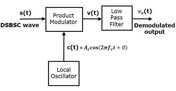
In this process, the message signal can be extracted from DSBSC wave by multiplying it with a carrier, having the same frequency and the phase of the carrier used in DSBSC modulation. The resulting signal is then passed through a Low Pass Filter. Output of this filter is the desired message signal.
Let the DSBSC wave be
$$s\left ( t \right )= A_c \cos\left ( 2 \pi f_ct \right )m \left ( t \right )$$
The output of the local oscillator is
$$c\left ( t \right )= A_c \cos\left ( 2 \pi f_ct+ \phi \right )$$
Where, $\phi$ is the phase difference between the local oscillator signal and the carrier signal, which is used for DSBSC modulation.
From the figure, we can write the output of product modulator as
$$v\left ( t \right )=s\left ( t \right )c\left ( t \right )$$
Substitute, $s\left ( t \right )$ and $c\left ( t \right )$ values in the above equation.
$$\Rightarrow v\left ( t \right )=A_c \cos \left ( 2 \pi f_ct \right )m\left ( t \right )A_c \cos \left ( 2 \pi f_ct + \phi \right )$$
$={A_{c}}^{2} \cos \left ( 2 \pi f_ct \right ) \cos \left ( 2 \pi f_ct + \phi \right )m\left ( t \right )$
$=\frac{{A_{c}}^{2}}{2}\left [ \cos\left ( 4 \pi f_ct+ \phi \right )+ \cos \phi \right ]m\left ( t \right )$
$$v\left ( t \right )=\frac{{A_{c}}^{2}}{2} \cos\phi m\left ( t \right )+\frac{{A_{c}}^{2}}{2} \cos \left ( 4 \pi f_ct+ \phi \right )m\left ( t \right )$$
In the above equation, the first term is the scaled version of the message signal. It can be extracted by passing the above signal through a low pass filter.
Therefore, the output of low pass filter is
$$v_0t=\frac{{A_{c}}^{2}}{2} \cos \phi m \left ( t \right )$$
The demodulated signal amplitude will be maximum, when $\phi=0^0$. That’s why the local oscillator signal and the carrier signal should be in phase, i.e., there should not be any phase difference between these two signals.
The demodulated signal amplitude will be zero, when $\phi=\pm 90^0$. This effect is called as quadrature null effect.
Costas Loop
Costas loop is used to make both the carrier signal (used for DSBSC modulation) and the locally generated signal in phase. Following is the block diagram of Costas loop.

Costas loop consists of two product modulators with common input $s\left ( t \right )$, which is DSBSC wave. The other input for both product modulators is taken from Voltage Controlled Oscillator (VCO) with $-90^0$ phase shift to one of the product modulator as shown in figure.
We know that the equation of DSBSC wave is
$$s\left ( t \right )=A_c \cos\left ( 2 \pi f_ct \right )m\left ( t \right )$$
Let the output of VCO be
$$c_1\left ( t \right )=\cos\left ( 2 \pi f_ct + \phi\right )$$
This output of VCO is applied as the carrier input of the upper product modulator.
Hence, the output of the upper product modulator is
$$v_1\left ( t \right )=s\left ( t \right )c_1\left ( t \right )$$
Substitute, $s\left ( t \right )$ and $c_1\left ( t \right )$ values in the above equation.
$$\Rightarrow v_1\left ( t \right )=A_c \cos \left ( 2 \pi f_ct \right )m\left ( t \right ) \cos\left ( 2 \pi f_ct + \phi \right )$$
After simplifying, we will get $v_1\left ( t \right )$ as
$$v_1\left ( t \right )=\frac{A_c}{2} \cos \phi m\left ( t \right )+\frac{A_c}{2} \cos\left ( 4 \pi f_ct + \phi \right )m\left ( t \right )$$
This signal is applied as an input of the upper low pass filter. The output of this low pass filter is
$$v_{01}\left ( t \right )=\frac{A_c}{2} \cos \phi m\left ( t \right )$$
Therefore, the output of this low pass filter is the scaled version of the modulating signal.
The output of $-90^0$ phase shifter is
$$c_2\left ( t \right )=cos\left ( 2 \pi f_ct + \phi-90^0 \right )= \sin\left ( 2 \pi f_ct + \phi \right )$$
This signal is applied as the carrier input of the lower product modulator.
The output of the lower product modulator is
$$v_2\left ( t \right )=s\left ( t \right )c_2\left ( t \right )$$
Substitute, $s\left ( t \right )$ and $c_2\left ( t \right )$ values in the above equation.
$$\Rightarrow v_2\left ( t \right )=A_c \cos\left ( 2 \pi f_ct \right )m\left ( t \right ) \sin \left ( 2 \pi f_ct + \phi \right )$$
After simplifying, we will get $v_2\left ( t \right )$ as
$$v_2\left ( t \right )=\frac{A_c}{2} \sin \phi m\left ( t \right )+\frac{A_c}{2} \sin \left ( 4 \pi f_ct+ \phi \right )m\left ( t \right )$$
This signal is applied as an input of the lower low pass filter. The output of this low pass filter is
$$v_{02}\left ( t \right )=\frac{A_c}{2} \sin \phi m\left ( t \right )$$
The output of this Low pass filter has $-90^0$ phase difference with the output of the upper low pass filter.
The outputs of these two low pass filters are applied as inputs of the phase discriminator. Based on the phase difference between these two signals, the phase discriminator produces a DC control signal.
This signal is applied as an input of VCO to correct the phase error in VCO output. Therefore, the carrier signal (used for DSBSC modulation) and the locally generated signal (VCO output) are in phase.